Toyota Tacoma (2015-2018) Service Manual: Parts Location
PARTS LOCATION
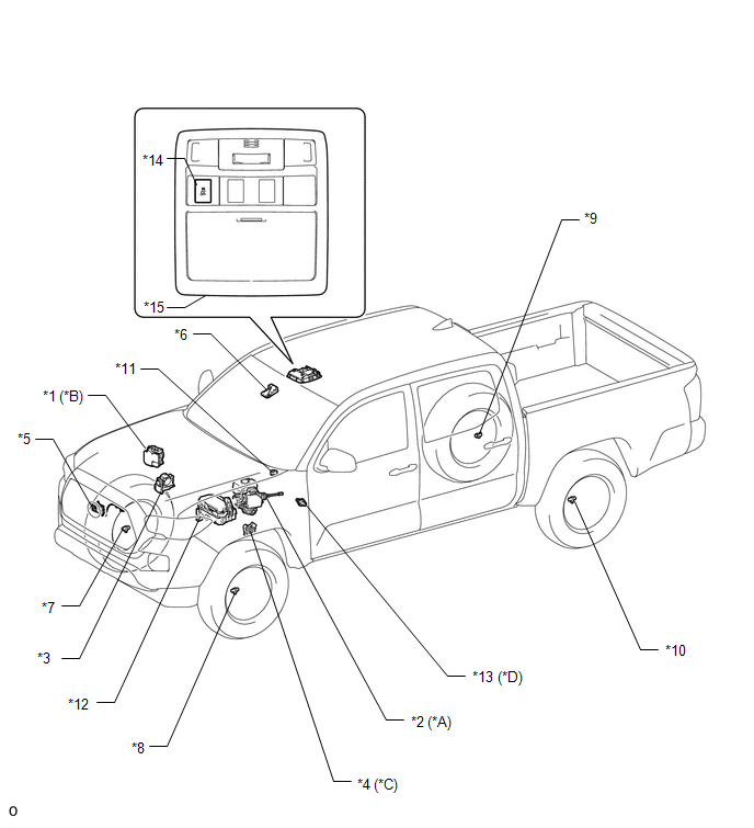
ILLUSTRATION
|
*A |
for Hydraulic Brake Booster |
*B |
for Vacuum Brake Booster |
|
*C |
for Automatic Transmission |
*D |
for Manual Transmission |
|
*1 |
SKID CONTROL ECU (BRAKE ACTUATOR ASSEMBLY) |
*2 |
SKID CONTROL ECU (MASTER CYLINDER SOLENOID) |
|
*3 |
THROTTLE BODY WITH MOTOR ASSEMBLY |
*4 |
PARK/NEUTRAL POSITION SWITCH |
|
*5 |
MILLIMETER WAVE RADAR SENSOR ASSEMBLY |
*6 |
FORWARD RECOGNITION CAMERA |
|
*7 |
FRONT SPEED SENSOR RH |
*8 |
FRONT SPEED SENSOR LH |
|
*9 |
REAR SPEED SENSOR RH |
*10 |
REAR SPEED SENSOR LH |
|
*11 |
SKID CONTROL BUZZER |
*12 |
ENGINE ROOM RELAY BLOCK - IG2 FUSE - EFI NO. 1 FUSE - ETCS FUSE - STOP FUSE - STOP RELAY |
|
*13 |
NEUTRAL POSITION SWITCH |
*14 |
VSC OFF SWITCH |
|
*15 |
ROOF CONSOLE BOX ASSEMBLY |
- |
- |
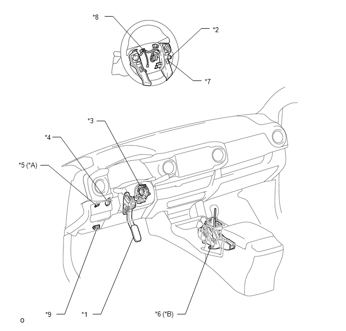
ILLUSTRATION
|
*A |
for Manual Transmission |
*B |
for Automatic Transmission |
|
*1 |
ACCELERATOR PEDAL SENSOR ASSEMBLY |
*2 |
CRUISE CONTROL MAIN SWITCH |
|
*3 |
STEERING ANGLE SENSOR (SPIRAL CABLE WITH SENSOR SUB-ASSEMBLY) |
*4 |
STOP LIGHT SWITCH ASSEMBLY |
|
*5 |
CLUTCH SWITCH ASSEMBLY |
*6 |
TRANSMISSION CONTROL SWITCH (TRANSMISSION FLOOR SHIFT ASSEMBLY ) |
|
*7 |
DISTANCE CONTROL SWITCH (STEERING PAD SWITCH ASSEMBLY) |
*8 |
CRUISE CONTROL SWITCH WIRE |
|
*9 |
DLC3 |
- |
- |
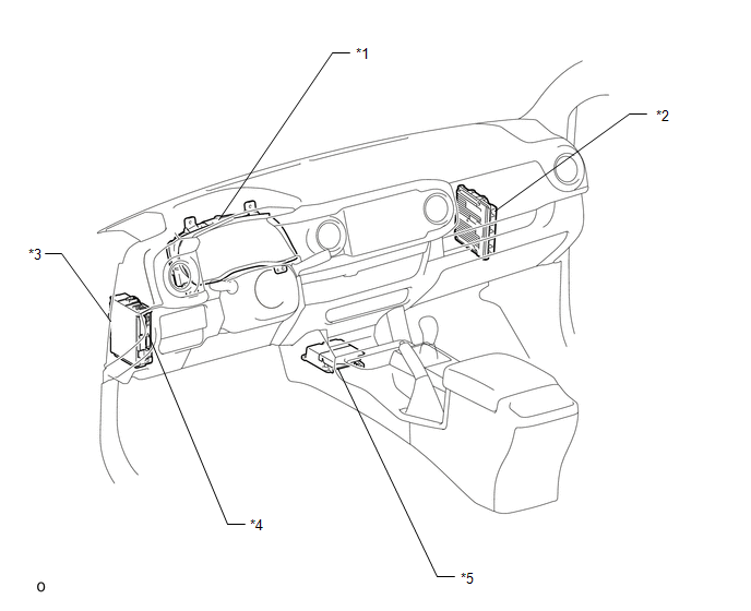
ILLUSTRATION
|
*1 |
COMBINATION METER ASSEMBLY |
*2 |
ECM |
|
*3 |
DRIVER SIDE JUNCTION BLOCK - IG1 NO. 2 FUSE - ECU-IG NO. 2 FUSE - IG1 NO. 1 FUSE - BKUP LP NO. 3 FUSE |
*4 |
MAIN BODY ECU (MULTIPLEX NETWORK BODY ECU) |
|
*5 |
YAW RATE AND ACCELERATION SENSOR (AIRBAG SENSOR ASSEMBLY) |
- |
- |
 Definition Of Terms
DEFINITION OF TERMS
Term
Definition
Monitor Description
Description of what the ECM monitors and how it detects malfunctions
(monitoring purpose ...
 System Diagram
SYSTEM DIAGRAM
Communication Table
Sender
Receiver
Signal
Line
ECM
Millimeter Wave Radar Sensor Assembly
...
Other materials:
Problem Symptoms Table
PROBLEM SYMPTOMS TABLE
NOTICE:
When replacing the skid control ECU (brake actuator assembly), sensor, etc.,
turn the ignition switch off.
HINT:
Use the table below to help determine the cause of problem symptoms.
If multiple suspected areas are listed, the potential causes of the s ...
Installation
INSTALLATION
CAUTION / NOTICE / HINT
HINT:
Use the same procedure for both the LH and RH sides.
The procedure described below is for the LH side.
PROCEDURE
1. INSTALL HEADLIGHT ASSEMBLY
(a) Connect the connectors.
(b) Engage the clamp to install the headlight assembly.
(c) ...
Indicator Circuit
DESCRIPTION
The forward recognition camera sends indicator illumination request signals to
the combination meter assembly via CAN communication.
CAUTION / NOTICE / HINT
NOTICE:
When replacing the combination meter assembly, always replace it with a new one.
If a combination meter assembly wh ...
