Toyota Tacoma (2015-2018) Service Manual: System Description
SYSTEM DESCRIPTION
1. FRONT PASSENGER OCCUPANT CLASSIFICATION SYSTEM
(a) General Description
(1) The front passenger occupant detection ECU determines whether the front passenger seat is occupied by an adult or child (with child seat) or is unoccupied, based on the load that is applied to the front passenger seat and whether the seat belt is buckled. The system restricts the deployment of the front passenger airbag, front passenger side airbag, and the front passenger seat belt pretensioner in accordance with this judgment. The result is informed to the driver through the airbag ON/OFF indicator illumination.
(b) System Configuration
(1) This system consists of the occupant detection ECU, occupant classification sensors, airbag ON/OFF indicator, seat belt buckle switches, and airbag sensor assembly.
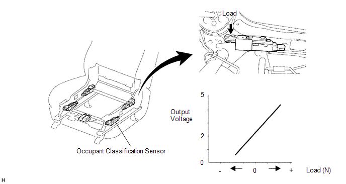
(c) Occupant Detection ECU and Sensor
(1) The occupant classification sensors are installed on four brackets connecting the seat rail and the seat frame. The resistance values of these sensors, which vary in accordance with the load that acts on the brackets, are transmitted to the occupant detection ECU as signals. Upon receipt of the signals, the ECU determines the front passenger seat occupant conditions.
 Initialization
INITIALIZATION
1. ZERO POINT CALIBRATION
NOTICE:
Make sure that the front passenger seat is not occupied before performing the
operation.
HINT:
Perform the zero point calibration and sensitivit ...
 System Diagram
SYSTEM DIAGRAM
...
Other materials:
Steering Angle Sensor Communication Stop Mode
DESCRIPTION
Detection Item
Symptom
Trouble Area
Steering Angle Sensor Communication Stop Mode
Either condition is met:
Communication stop for "Spiral cable (Steering Angle Sensor)"
is indicated on the "C ...
Precaution
PRECAUTION
IGNITION SWITCH EXPRESSIONS
(a) The type of ignition switch used on this model differs according to the specifications
of the vehicle. The expressions listed in the table below are used in this section.
Expression
Ignition Switch (Position)
Engine Swi ...
Some Alarm Functions do not Operate
DESCRIPTION
When the alarm sounds, the following alarm functions operate: the roof console
box assembly and No. 1 room light assembly illuminates, and the headlights, taillights
and hazard lights flash, and the security horn and vehicle horn sound intermittently.
WIRING DIAGRAM
CAUTION / ...
