Toyota Tacoma (2015-2018) Service Manual: System Diagram
SYSTEM DIAGRAM
 System Description
SYSTEM DESCRIPTION
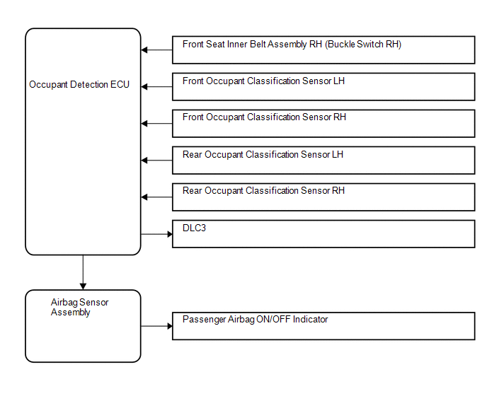
1. FRONT PASSENGER OCCUPANT CLASSIFICATION SYSTEM
(a) General Description
(1) The front passenger occupant detection ECU determines whether the front passenger
seat is occupied ...
 Diagnosis System
DIAGNOSIS SYSTEM
1. CHECK DLC3
(a) The vehicle's ECU uses the ISO 9141-2 for communication protocol. The terminal
arrangement of the DLC3 complies with SAE J1962 and matches the ISO 15765-4 fo ...
Other materials:
System Diagram
SYSTEM DIAGRAM
Transmitting ECU (Transmitter)
Receiving ECU
Signal
Communication Method
4 wheel drive control ECU
Skid control ECU (Brake actuator assembly)
High-Low actuator fail
4WD status ...
Terminals Of Ecu
TERMINALS OF ECU
1. CHECK 4 WHEEL DRIVE CONTROL ECU
Text in Illustration
*a
Component with harness connected
(4 Wheel Drive Control ECU)
-
-
(a) Measure the resistance and voltage according to the value(s) in the table
below.
...
Removal
REMOVAL
PROCEDURE
1. REMOVE REAR SEAT CUSHION ASSEMBLY
(a) Remove the 2 bolts and rear seat cushion assembly.
2. REMOVE REAR SEATBACK HINGE COVER
(a) for LH Side:
(1) Disengage the 6 claws to remove the 2 rear seatback hinge cov ...
