Toyota Tacoma (2015-2018) Service Manual: Ignition Switch
Components
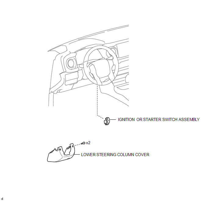
COMPONENTS
ILLUSTRATION
Removal
REMOVAL
PROCEDURE
1. REMOVE LOWER STEERING COLUMN COVER
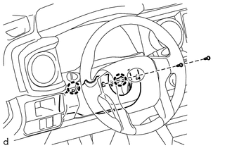
(a) Remove the 2 screws.
(b) Disengage the 2 claws and remove the lower steering column cover.
2. REMOVE IGNITION OR STARTER SWITCH ASSEMBLY
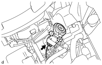
(a) Disconnect the connector.
(b) Disengage the 2 claws and remove the ignition or starter switch assembly.
Inspection
INSPECTION
PROCEDURE
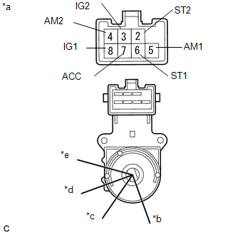
1. INSPECT IGNITION OR STARTER SWITCH ASSEMBLY
|
(a) Check the resistance. Text in Illustration
(1) Measure the resistance according to the value(s) in the table below. Standard Resistance:
If the result is not as specified, replace the ignition or starter switch assembly. |
|
Installation
INSTALLATION
PROCEDURE
1. INSTALL IGNITION OR STARTER SWITCH ASSEMBLY
(a) Engage the 2 claws and install the ignition or starter switch assembly.
(b) Connect the connector.
2. INSTALL LOWER STEERING COLUMN COVER
(a) Engage the 2 claws and install the lower steering column cover.
(b) Install the 2 screws.
HINT:
Turn the steering wheel to the right and left as necessary to install the 2 screws.
 Engine Switch
Components
COMPONENTS
ILLUSTRATION
Inspection
INSPECTION
PROCEDURE
1. INSPECT ENGINE SWITCH
(a) Measure the resistance according to the value(s) in the table below.
Text in Illustration ...

Other materials:
Front Camera Module Circuit (C1AA0)
DESCRIPTION
When an internal malfunction is detected in the forward recognition camera, DTC
C1AA0 is stored.
DTC No.
Detection Item
DTC Detection Condition
Trouble Area
C1AA0
Front Camera Module Circuit
3 seconds ...
Reassembly
REASSEMBLY
PROCEDURE
1. INSTALL NO. 3 REAR BODY NAME PLATE (for 2GR-FKS)
2. INSTALL NO. 2 REAR BODY NAME PLATE (for 4WD)
3. INSTALL SIDE GATE SUPPORT FEMALE HINGE RH
(a) Engage the claw to install the side gate support female hinge RH.
...
Dtc Check / Clear
DTC CHECK / CLEAR
1. CHECK DTC
(a) Connect the Techstream to the DLC3.
(b) Turn the ignition switch to ON.
(c) Turn the Techstream on.
(d) Enter the following menus: Body Electrical / (desired system) / Trouble Codes.
(e) Check the details of the DTC(s) (See page
).
2. CLEAR DTC
(a) Connec ...
