Toyota Tacoma (2015-2018) Service Manual: System Description
SYSTEM DESCRIPTION
1. DESCRIPTION OF SYSTEM
(a) When the tire pressure warning system detects that the tire pressure of a tire is lower than the threshold, it will inform the driver using a warning light.
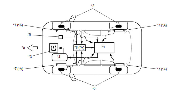
(b) The tire pressure warning ECU and receiver receives the transmitter ID, temperature and tire pressure information from the tire pressure warning valve and transmitters shown in the following illustration. This information is used to determine when the pressure in one of the tires has dropped.
 Text in Illustration
|
*A |
w/ Tire Inflation Pressure Display Function |
- |
- |
|
*1 |
Tire Pressure Warning ECU and Receiver |
*2 |
Tire Pressure Warning Valve and Transmitter |
|
*3 |
Combination Meter Assembly - Tire Pressure Warning Light |
*4 |
Main Body ECU (Multiplex Network Body ECU) |
|
*5 |
Tire Pressure Warning Reset Switch |
*6 |
Skid Control ECU |
|
*7 |
Speed Sensor |
- |
- |
|
*a |
Front |
- |
- |
2. DESCRIPTION OF TIRE POSITION IDENTIFICATION FUNCTION (w/ Tire Inflation Pressure Display Function)
(a) The tire inflation pressure display function displays the position and pressure of each tire on the multi-information display.
(b) The tire position can be identified using any of the following 3 methods:
(1) Using the Techstream, manually enter the tire position for each transmitter ID.
(2) Perform initialization to clear the existing tire position information, then drive the vehicle at 37 km/h (23 mph) or more for 10 minutes or more until each tire position is automatically identified.
(3) Without performing initialization, drive the vehicle as normal until each tire position is automatically updated.
NOTICE:
- Identifying the tire position automatically without performing initialization by driving the vehicle as normal may take longer than other methods.
- The previous tire positions will be displayed until they are automatically updated.
3. DESCRIPTION OF REGISTRATION
(a) When tires and wheels are replaced, always ensure that each transmitter ID is correctly registered.
(b) When one or more of the tire pressure warning valve and transmitters or the tire pressure warning ECU and receiver is replaced, the transmitter IDs for all of the tire pressure warning valve and transmitters must be re-registered. Before registering the transmitter ID of the new tire pressure warning valve and transmitter, check the Data List and record all of the transmitter IDs that are already registered.
4. TIRE PRESSURE WARNING RESET SWITCH
(a) By operating the tire pressure warning reset switch, the tire pressure warning ECU and receiver can be set to issue a warning at an inflation pressure that corresponds to the type of tires fitted to the vehicle. Therefore, the warning threshold must be set to the proper value in order to comply with local regulations.
(b) Operate the tire pressure warning reset switch only after the inflation pressures of all tires (except the compact spare tire) have been adjusted on the vehicle.
5. DESCRIPTION OF INITIALIZATION
(a) During initialization, the tire pressure warning valve and transmitters measure the inflation pressure of the tires, and register the signals that are transmitted into the tire pressure warning ECU and receiver at a frequency of about once per minute. The initialization process is completed when signals from all tires (except the compact spare tire) have been received.
(b) Perform initialization in the following cases:
(1) Before delivery of a new vehicle.
(2) After replacement of the tire pressure warning ECU and receiver*.
(3) After replacement of a tire pressure warning valve and transmitter*.
(4) When the specified tire pressure changes due to the use of a different size or type of tire.
(5) When the specified tire pressure changes due to a change in the vehicle load, the speed range that the vehicle will be used in, etc.
(6) When a tire rotation is performed and the specified tire pressures are different for the front and rear of the vehicle.
HINT:
*: Perform initialization after the transmitter ID registration is completed.
6. FUNCTION OF MAIN COMPONENTS
|
Component |
Component |
|---|---|
|
Tire Pressure Warning ECU and Receiver |
w/ Tire Inflation Pressure Display Function:
|
|
Tire Pressure Warning Valve and Transmitter |
Detects the pressure and internal temperature of the tire and transmits the measured values and the ID code to the tire pressure warning ECU and receiver. w/ Tire Inflation Pressure Display Function:
|
|
Tire Pressure Warning Reset Switch |
Stores the warning threshold determined by the current tire pressure as the set pressure in the tire pressure warning ECU and receiver when operated. |
|
Combination Meter Assembly |
Transmits the vehicle speed signal to the tire pressure warning ECU and receiver. |
|
Tire Pressure Warning Light |
|
|
Main Body ECU (Multiplex Network Body ECU) |
w/ Tire Inflation Pressure Display Function:
|
 System Diagram
SYSTEM DIAGRAM
HINT:
Each tire pressure warning valve and transmitter sends its transmitter ID, temperature
and tire pressure information to the tire pressure warning ECU and receiver.
...
 Initialization
INITIALIZATION
NOTICE:
Initialization can only be performed for vehicles with a tire pressure
warning reset switch.
If initialization is performed, the existing tire positions will b ...
Other materials:
Power Window Switch Malfunction (B2312)
DESCRIPTION
The power window regulator motor assembly is operated by the power window regulator
master switch assembly or power window regulator switch assembly. The power window
regulator motor assembly has motor, regulator and ECU functions.
This DTC is output when the ECU built into the reg ...
Data List / Active Test
DATA LIST / ACTIVE TEST
1. DATA LIST
HINT:
Using the Techstream to read the Data List allows the values or states of switches,
sensors, actuators and other items to be read without removing any parts. This non-intrusive
inspection can be very useful because intermittent conditions or signals ...
Disposal
DISPOSAL
CAUTION / NOTICE / HINT
CAUTION:
Before performing pre-disposal deployment of any SRS part, review and closely
follow all applicable environmental and hazardous material regulations. Pre-disposal
deployment may be considered hazardous material treatment.
PROCEDURE
1. PRECAUTION
...
