Toyota Tacoma (2015-2018) Service Manual: Inspection
INSPECTION
PROCEDURE
1. INSPECT FRONT SEAT CUSHION HEATER ASSEMBLY
|
(a) Check the operation of the front seat cushion heater assembly. (1) Apply battery voltage and check the operation of the front seat cushion heater assembly. OK:
NOTICE: Immediately after confirming that the front seat cushion heater assembly is functioning normally, remove the battery leads. Failing to do so may cause the front seat cushion heater assembly to overheat. If the result is not as specified, replace the front seat cushion heater assembly. |
|
(b) Check the operation of the thermostat.
(1) Apply battery voltage and check the operation of the front seat cushion heater assembly.
OK:
|
Connection |
Condition |
Specified Condition |
|---|---|---|
|
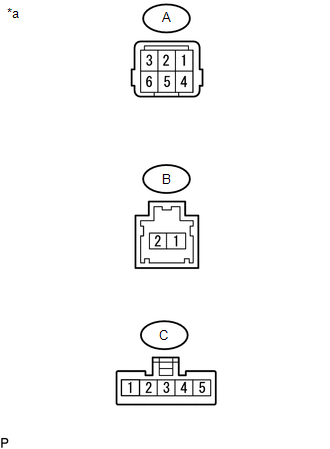
Battery positive (+) → Terminal A-3 Battery negative (-) → Terminal C-5 |
Always |
Seat cushion heater temperature becomes below 55°C (129°F) |
NOTICE:
Immediately after confirming that the front seat cushion heater assembly is functioning normally, remove the battery leads. Failing to do so may cause the front seat cushion heater assembly to overheat.
If the result is not as specified, replace the front seat cushion heater assembly.
(c) Check the resistance.
(1) Measure the resistance according to the value(s) in the table below.
Standard Resistance:
|
Tester Connection |
Connection |
Specified Condition |
|---|---|---|
|
A-1 - C-3 |
Always |
Below 1 Ω |
|
A-2 - C-1 |
Always |
Below 1 Ω |
|
A-5 - C-5 - B-2 |
Always |
Below 1 Ω |
 Components
COMPONENTS
ILLUSTRATION
*A
for Driver Side
-
-
*1
FRONT SEAT CUSHION HEATER ASSEMBLY
*2
SEPARATE TYPE ...
 Removal
REMOVAL
PROCEDURE
1. REMOVE FRONT SEAT ASSEMBLY (for Driver Side)
(See page )
2. REMOVE FRONT SEAT ASSEMBLY (for Front Passenger Side)
(See page )
3. REMOVE SEPARATE TYPE FRONT SEAT CUSHION CO ...
Other materials:
Radio Receiver Power Source Circuit
DESCRIPTION
This is the power source circuit to operate the radio and display receiver assembly.
WIRING DIAGRAM
CAUTION / NOTICE / HINT
NOTICE:
Inspect the fuses for circuits related to this system before performing
the following inspection procedure.
PROCEDURE
...
Rear Speed Sensor RH Output Malfunction (C1415,C1416)
DESCRIPTION
Refer to DTCs C1403 and C1404 (See page ).
DTC No.
Detection Item
DTC Detection Condition
Trouble Area
C1415
Rear Speed Sensor RH Output Malfunction
Any of the following is detected:
An op ...
Installation
INSTALLATION
PROCEDURE
1. INSTALL AIR CONDITIONING UNIT ASSEMBLY
(a) Temporary install the air conditioning unit assembly.
(b) Insert the bracket hook into the holes of the reinforcement bracket, and
temporary install the instrument panel reinforcement assembly.
(c) Install the instrument p ...
