Toyota Tacoma (2015-2018) Service Manual: Terminals Of Ecu
TERMINALS OF ECU
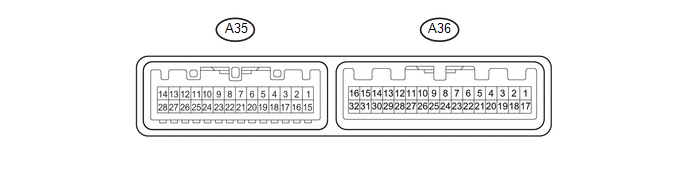
1. AIR CONDITIONING AMPLIFIER ASSEMBLY
HINT:
Check from the rear of the connector while it is connected to the air conditioning amplifier assembly.
|
Terminal No. (Symbol) |
Wiring Color |
Terminal Description |
Condition |
Specified Condition |
|---|---|---|---|---|
|
A35-1 (TAM) - A36-28 (SG-8) |
W - LG |
Ambient temperature sensor signal |
|
1.35 to 1.75 V |
|
0.9 to 1.2 V |
|||
|
A35-2 (PRE) - A36-10 (GND) |
V - W-B |
Air conditioner pressure sensor signal |
|
4.71 V or higher |
|
Below 0.74 V |
|||
|
0.74 to 4.71 V |
|||
|
A35-3 (TPO) - A35-19 (SG-6) |
B - L |
Mode damper position sensor signal |
|
4.43 to 4.53 V |
|
0.47 to 0.57 V |
|||
|
A35-4 (TPR) - A35-18 (SG-5) |
G - GR |
Air mix damper position sensor (for front passenger side) signal |
|
4.45 to 4.55 V |
|
0.45 to 0.55 V |
|||
|
A35-5 (TPL) - A35-17 (SG-4) |
V - R |
Air mix damper position sensor (for driver side) signal |
|
4.45 to 4.55 V |
|
0.45 to 0.55 V |
|||
|
A35-6 (TPI) - A35-16 (SG-3) |
LG -V |
Air inlet damper position sensor signal |
|
1.63 to 1.73 V |
|
3.27 to 3.37 V |
|||
|
A35-7 (LOCK) - A36-10 (GND) |
G - W-B |
A/C lock sensor signal |
|
Pulse generation (See waveform 1) |
|
A35-10 (MGC) - A36-10 (GND) |
G - W-B |
Magnetic clutch operation signal |
|
11 to 14 V |
|
Below 1 V |
|||
|
A35-11 (AMDH) - A36-10 (GND) |
BE - W-B |
Air mix damper servo motor (for driver side) operating signal |
|
11 to 14 V (Servo motor operating) |
|
A35-12 (AMDC) - A36-10 (GND) |
SB - W-B |
Air mix damper servo motor (for driver side) operating signal |
|
11 to 14 V (Servo motor operating) |
|
A35-13 (AMPH) - A36-10 (GND) |
Y - W-B |
Air mix damper servo motor (for front passenger side) operating signal |
|
11 to 14 V (Servo motor (Servo motor operating) |
|
A35-14 (AMPC) - A36-10 (GND) |
W - W-B |
Air mix damper servo motor (for front passenger side) operating signal |
|
11 to 14 V (Servo motor operating) |
|
A35-16 (SG-3) - Body ground |
V - Body ground |
Ground for air inlet damper position sensor |
Always |
Below 1 Ω |
|
A35-17 (SG-4) - Body ground |
R - Body ground |
Ground for air mix damper position sensor (for driver side) |
Always |
Below 1 Ω |
|
A35-18 (SG-5) - Body ground |
GR - Body ground |
Ground for air mix damper position sensor (for front passenger side) |
Always |
Below 1 Ω |
|
A35-19 (SG-6) - Body ground |
L - Body ground |
Ground for mode damper position sensor |
Always |
Below 1 Ω |
|
A35-22 (AC1) - A36-10 (GND) |
BE - W-B |
Compressor operation signal |
|
11 to 14 V |
|
Below 1 V |
|||
|
A35-25 (AIF) - A36-10 (GND) |
P - W-B |
Air inlet damper servo motor operating signal |
|
11 to 14 V (Servo motor operating) |
|
A35-26 (AIR) - A36-10 (GND) |
B - W-B |
Air inlet damper servo motor operating signal |
|
11 to 14 V (Servo motor operating) |
|
A35-27 (AOF) - A36-10 (GND) |
LG - W-B |
Mode damper servo motor operating signal |
|
11 to 14 V (Servo motor operating) |
|
A35-28 (AOD) - A36-10 (GND) |
R - W-B |
Mode damper servo motor operating signal |
|
11 to 14 V (Servo motor operating) |
|
A35-30 (S5-5) - A36-10 (GND) |
G - W-B |
Power supply for mode damper position sensor |
Ignition switch off |
Below 1 V |
|
Ignition switch ON |
4.75 to 5.25 V |
|||
|
A36-1 (IG+) - A36-10 (GND) |
GR - W-B |
Power source (IG) |
Ignition switch ON |
11 to 14 V |
|
Ignition switch off |
Below 1 V |
|||
|
A36-4 (ACT) - A36-10 (GND) |
R - W-B |
Compressor operation signal |
|
Below 1 V |
|
4.75 to 5.25 V |
|||
|
A36-7 (HRLY) - A36-10 (GND) |
Y - W-B |
HTR relay operation signal |
|
11 to 14 V |
|
Below 1 V |
|||
|
A36-8 (CANH) |
L |
CAN communication system |
- |
- |
|
A36-9 (CANL) |
W |
CAN communication system |
- |
- |
|
A36-10 (GND) - Body ground |
W-B - Body ground |
Ground for main power supply |
Always |
Below 1 Ω |
|
A36-11 (LIN1) - A36-10 (GND) |
SB - W-B |
LIN communication signal |
Ignition switch ON |
Pulse generation |
|
A36-12 (S5-1) - A36-10 (GND) |
SB - W-B |
Power supply for air conditioner pressure sensor |
Ignition switch off |
Below 1 V |
|
Ignition switch ON |
4.5 to 5.5 V |
|||
|
A36-13 (S5-2) - A36-10 (GND) |
Y - W-B |
Power supply for air inlet damper position sensor |
Ignition switch off |
Below 1 V |
|
Ignition switch ON |
4.75 to 5.25 V |
|||
|
A36-14 (S5-3) - A36-10 (GND) |
Y - W-B |
Power supply for air mix damper position sensor (for driver side) |
Ignition switch off |
Below 1 V |
|
Ignition switch ON |
4.75 to 5.25 V |
|||
|
A36-15 (TE) - A36-27 (SG-7) |
B - GR |
Evaporator temperature sensor signal |
|
1.7 to 2.1 V |
|
0.9 to 1.3 V |
|||
|
A36-16 (TR) - A36-26 (SG-1) |
R - BR |
Room temperature sensor signal |
|
1.8 to 2.2 V |
|
1.2 to 1.6 V |
|||
|
A36-17 (B) - A36-10 (GND) |
LG - W-B |
Power source (Back-up) |
Always |
11 to 14 V |
|
A36-19 (PTC1) - A36-10 (GND)*1 |
V - W-B |
Quick heater operation signal |
|
11 to 14 V |
|
Below 1 V |
|||
|
A36-20 (PTC2) - A36-10 (GND)*1 |
W - W-B |
Quick heater operation signal |
|
11 to 14 V |
|
Below 1 V |
|||
|
A36-21 (PTC3) - A36-10 (GND)*1 |
P - W-B |
Quick heater operation signal |
|
11 to 14 V |
|
Below 1 V |
|||
|
A36-23 (BLW) - A36-10 (GND) |
BE - W-B |
Blower motor speed control signal |
|
Pulse generation (See waveform 2) |
|
A36-26 (SG-1) - Body ground |
BR - Body ground |
Ground for room temperature sensor |
Always |
Below 1 Ω |
|
A36-27 (SG-7) - Body ground |
GR - Body ground |
Ground for evaporator temperature sensor |
Always |
Below 1 Ω |
|
A36-28 (SG-8) - Body ground |
LG - Body ground |
Ground for air conditioner pressure sensor, ambient temperature sensor, A/C lock sensor |
Always |
Below 1 Ω |
|
A36-29 (S5-4) - A36-10 (GND) |
R - W-B |
Power supply for air mix damper position sensor (for front passenger side) |
Ignition switch off |
Below 1 V |
|
Ignition switch ON |
4.75 to 5.25 V |
- *1: w/ PTC Heater
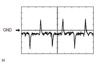
(a) Waveform 1:
|
Item |
Content |
|---|---|
|
Terminal No. |
A35-7 (LOCK) - A36-10 (GND) |
|
Tool Setting |
200 mV/DIV., 10 ms./DIV. |
|
Vehicle Condition |
|
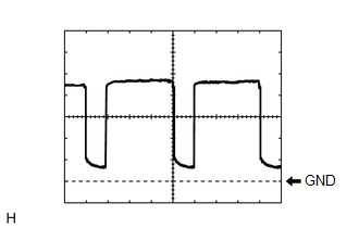
(b) Waveform 2:
|
Item |
Content |
|---|---|
|
Terminal No. |
A36-23 (BLW) - A36-10 (GND) |
|
Tool Setting |
1 V/DIV., 500 Îỳs./DIV. |
|
Vehicle Condition |
|
2. AIR CONDITIONING CONTROL ASSEMBLY

HINT:
Check from the rear of the connector while it is connected to the air conditioning control assembly.
|
Terminal No. (Symbol) |
Wiring Color |
Terminal Description |
Condition |
Specified Condition |
|---|---|---|---|---|
|
A33-8 (IG+) - A33-1 (GND) |
LG - W-B |
Power source (IG) |
Ignition switch off |
Below 1 V |
|
Ignition switch ON |
11 to 14 V |
|||
|
A33-1 (GND) - Body ground |
W-B - Body ground |
Ground for air conditioning control assembly |
Always |
Below 1 Ω |
|
A33-2 (STX) - A33-1 (GND) |
SB - W-B |
LIN communication signal |
Ignition switch ON |
Pulse generation |
3. ECM (See page .gif) )
)
 Problem Symptoms Table
PROBLEM SYMPTOMS TABLE
HINT:
Use the table below to help determine the cause of problem symptoms.
If multiple suspected areas are listed, the potential causes of the symptoms
are lis ...
 Data List / Active Test
DATA LIST / ACTIVE TEST
1. DATA LIST
Using the Techstream to read the Data List allows the values or states of switches,
sensors, actuators and other items to be read without removing any parts. T ...
Other materials:
Dtc Check / Clear
DTC CHECK / CLEAR
1. DTC CHECK/CLEAR (When Using Techstream)
(a) Check the DTC.
(1) Turn the ignition switch off.
(2) Connect the Techstream to the DLC3.
(3) Turn the ignition switch to ON.
(4) Turn the Techstream on.
(5) Read the DTCs following the prompts on the Techstream screen. Enter the ...
Data List / Active Test
DATA LIST / ACTIVE TEST
1. READ DATA LIST
HINT:
Using the Techstream to read the Data List allows the values or states of switches,
sensors, actuators and other items to be read without removing any parts. This non-intrusive
inspection can be very useful because intermittent conditions or sig ...
Stereo Component Amplifier Power Source Circuit
DESCRIPTION
This circuit provides power to the stereo component amplifier assembly.
WIRING DIAGRAM
CAUTION / NOTICE / HINT
Inspect the fuses for circuits related to this system before performing the following
inspection procedure.
PROCEDURE
1.
CHECK HARNESS AND CONNE ...
