Toyota Tacoma (2015-2018) Service Manual: Steering Angle Sensor Power Source Voltage Malfunction (C1432)
DESCRIPTION
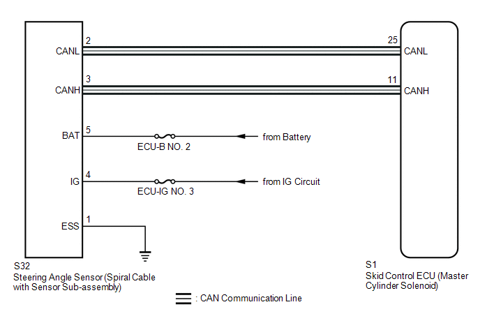
Steering angle sensor (spiral cable with sensor sub-assembly) signals are sent to the skid control ECU (master cylinder solenoid) via the CAN communication system. When there is a malfunction in the CAN communication system, it is detected by the steering angle sensor zero point malfunction diagnostic function.
|
DTC Code |
DTC Detection Condition |
Trouble Area |
|---|---|---|
|
C1432 |
A steering angle sensor power supply malfunction signal is received from the steering angle sensor. |
|
WIRING DIAGRAM
CAUTION / NOTICE / HINT
NOTICE:
Inspect the fuses for circuits related to this system before performing the following inspection procedure.
HINT:
- When the speed sensor or the yaw rate and acceleration sensor (airbag sensor assembly) has trouble, DTCs for the steering angle sensor (spiral cable with sensor sub-assembly) may be stored even when the steering angle sensor (spiral cable with sensor sub-assembly) is normal. When DTCs for the speed sensor or yaw rate and acceleration sensor (airbag sensor assembly) are output together with DTCs for the steering angle sensor (spiral cable with sensor sub-assembly), inspect and repair the speed sensor and yaw rate and acceleration sensor (airbag sensor assembly) first, and then inspect and repair the steering angle sensor (spiral cable with sensor sub-assembly).
PROCEDURE
|
1. |
CHECK CAN COMMUNICATION SYSTEM |
(a) Check for DTCs (See page .gif) ).
).
|
Result |
Proceed to |
|---|---|
|
CAN DTC is not output |
A |
|
CAN DTC is output |
B |
| B | .gif) |
GO TO CAN COMMUNICATION SYSTEM (HOW TO PROCEED WITH TROUBLESHOOTING) |
|
.gif)
|
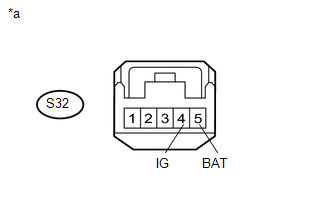
2. |
CHECK HARNESS AND CONNECTOR (IG, BAT TERMINAL) |
(a) Make sure that there is no looseness in the locking part and connecting part of the connectors.
(b) Disconnect the S32 steering angle sensor (spiral cable with sensor sub-assembly) connector.
|
(c) Measure the voltage according to the value(s) in the table below. Standard Voltage:
|
|
| NG | |
REPAIR OR REPLACE HARNESS OR CONNECTOR (POWER SOURCE CIRCUIT) |
|
|
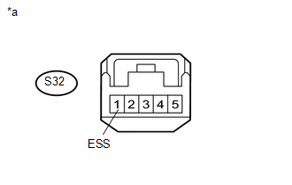
3. |
CHECK HARNESS AND CONNECTOR (ESS TERMINAL) |
(a) Turn the ignition switch off.
(b) Disconnect the S32 steering angle sensor (spiral cable with sensor sub-assembly) connector.
|
(c) Measure the resistance according to the value(s) in the table below. Standard Resistance:
|
|
| OK | |
REPLACE STEERING ANGLE SENSOR (SPIRAL CABLE WITH SENSOR SUB-ASSEMBLY) |
| NG | |
REPAIR OR REPLACE HARNESS OR CONNECTOR (GROUND CIRCUIT) |
 Open in Stop Light Switch Circuit (C1425)
DESCRIPTION
The skid control ECU (master cylinder solenoid) inputs stop light switch signals
and the brake operation condition.
The skid control ECU (master cylinder solenoid) has an open detectio ...
 Steering Angle Sensor Internal Circuit (C1433)
DESCRIPTION
Steering angle sensor (spiral cable with sensor sub-assembly) signals are sent
to the skid control ECU (master cylinder solenoid) via the CAN communication system.
When there is a mal ...
Other materials:
Utility
UTILITY
NOTICE:
If the forward recognition camera has been replaced due to a malfunction in the
lane departure alert system, be sure to perform Recognition Camera/Target Position
Memory and Optical Axis Learning. Otherwise all systems that use the forward recognition
camera may be affected.
...
Terminals Of Ecu
TERMINALS OF ECU
1. CHECK CERTIFICATION ECU (SMART KEY ECU ASSEMBLY)
(a) Disconnect the C27 and C29 certification ECU (smart key ECU assembly) connectors.
(b) Measure the voltage and resistance according to the value(s) in the table
below.
HINT:
Measure the values on the wire harness side w ...
Removal
REMOVAL
CAUTION / NOTICE / HINT
CAUTION:
Be sure to read Precaution thoroughly before servicing (See page
).
If the side airbag was deployed, replace the front seat airbag assembly
LH, front seatback cover and front seat frame with adjuster assembly with
the necessary part ...
