Toyota Tacoma (2015-2018) Service Manual: Removal
REMOVAL
CAUTION / NOTICE / HINT
CAUTION:
- Be sure to read Precaution thoroughly before servicing (See page
.gif) ).
). - If the side airbag was deployed, replace the front seat airbag assembly LH, front seatback cover and front seat frame with adjuster assembly with the necessary parts in accordance with the extent of the collision damage.
- Wear protective gloves. Sharp areas on the parts may injure your hands.
HINT:
- Use the same procedure for both the RH and LH sides.
- The procedure described below is for the LH side.
PROCEDURE
1. REMOVE SEATBACK COVER WITH PAD
(See page )
2. REMOVE FRONT SEAT AIRBAG ASSEMBLY LH
|
(a) Disengage the clamp. |
|
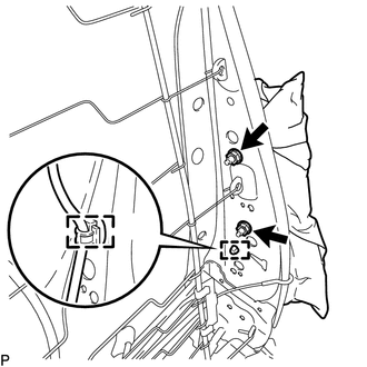
(b) Remove the 2 nuts and front seat airbag assembly LH.
CAUTION:
- The nuts must not be reused.
- Make sure that the front seatback main frame sub-assembly is not deformed. If it is, replace it with a new one.
 On-vehicle Inspection
ON-VEHICLE INSPECTION
PROCEDURE
1. INSPECT FRONT SEAT AIRBAG ASSEMBLY LH (for Vehicle not Involved in Collision)
(a) Perform a diagnostic system check (See page
).
...
 Disposal
DISPOSAL
CAUTION / NOTICE / HINT
CAUTION:
Before performing pre-disposal deployment of any SRS part, review and closely
follow all applicable environmental and hazardous material regulations. Pre ...
Other materials:
How To Proceed With Troubleshooting
CAUTION / NOTICE / HINT
HINT:
The vehicle stability control system troubleshooting procedures are
based on the premise that the CAN communication system is functioning normally.
Check the CAN communication system first before troubleshooting the vehicle
stability control system ...
AVC-LAN Circuit
DESCRIPTION
Each unit of the navigation system connected to the AVC-LAN (communication bus)
transfers the switch signals using the AVC-LAN.
If a short to +B or short to ground occurs in the AVC-LAN, the navigation system
will not function normally because communication is not possible.
WIRING ...
Brake System Malfunction (C1A50)
DESCRIPTION
When the pre-collision system is operating, the millimeter wave radar sensor
assembly sends brake control signals to the skid control ECU (master cylinder solenoid)*1
or skid control ECU (brake actuator assembly)*2.
If the millimeter wave radar sensor assembly receives a vehicle st ...
