Toyota Tacoma (2015-2018) Service Manual: SRS Warning Light does not Come ON
DESCRIPTION
See page .gif) .
.
WIRING DIAGRAM
See page .
CAUTION / NOTICE / HINT
NOTICE:
- Inspect the fuses for circuits related to this system before performing the following inspection procedure.
- After turning the ignition switch off, waiting time may be required
before disconnecting the cable from the battery terminal. Therefore, make
sure to read the disconnecting the cable from the battery terminal notice
before proceeding with work (See page
).
PROCEDURE
|
1. |
INSPECT BATTERY |
(a) Measure the voltage of the battery.
Standard Voltage:
|
Tester Connection |
Condition |
Specified Condition |
|---|---|---|
|
Battery |
Always |
11 to 14 V |
| NG | .gif) |
CHECK AND REPLACE BATTERY OR CHARGING SYSTEM |
|
.gif)
|
2. |
CHECK CONNECTION OF CONNECTORS |
(a) Turn the ignition switch off.
(b) Disconnect the cable from the negative (-) battery terminal, and wait for at least 90 seconds.
(c) Check that the connectors are properly connected to the airbag sensor assembly and the combination meter assembly.
OK:
The connectors are properly connected.
| NG | |
CONNECT CONNECTORS PROPERLY |
|
|
3. |
CHECK HARNESS AND CONNECTOR (SOURCE VOLTAGE OF COMBINATION METER ASSEMBLY) |
|
(a) Turn the ignition switch off. |
|
(b) Disconnect the cable from the negative (-) battery terminal, and wait for at least 90 seconds.
(c) Disconnect the connectors from the combination meter assembly.
(d) Connect the cable to the negative battery terminal, and wait for at least 2 seconds.
(e) Turn the ignition switch to ON.
(f) Measure the voltage according to the value(s) in the table below.
Standard Voltage:
|
Tester Connection |
Switch Condition |
Specified Condition |
|---|---|---|
|
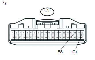
C9-20 (IG+) - C9-18 (ES) |
Ignition switch ON |
11 to 14 V |
|
*a |
Front view of wire harness connector (to Combination Meter Assembly) |
| NG | |
REPAIR OR REPLACE HARNESS OR CONNECTOR |
|
|
4. |
CHECK SRS WARNING LIGHT |
(a) Turn the ignition switch off.
(b) Disconnect the cable from the negative (-) battery terminal, and wait for at least 90 seconds.
(c) Connect the connector to the combination meter assembly.
(d) Connect the cable to the negative (-) battery terminal, and wait for at least 2 seconds.
(e) Turn the ignition switch to ON.
(f) Check the SRS warning light condition.
OK:
The SRS warning light turns off after the primary check period and comes on again after approximately 10 seconds.
HINT:
The primary check period lasts for approximately 6 seconds after the ignition switch is turned to ON.
| OK | |
REPLACE AIRBAG SENSOR ASSEMBLY |
| NG | |
REPLACE COMBINATION METER ASSEMBLY |
 Front Airbag Sensor RH Circuit Malfunction (B1610/13)
DESCRIPTION
The front airbag sensor RH consists of parts such as the diagnostic circuit and
the frontal detection sensor.
When the airbag sensor assembly receives signals from the frontal decelera ...
 SRS Warning Light Remains ON
DESCRIPTION
The SRS warning light is located on the combination meter assembly.
When the SRS condition is normal, the SRS warning light illuminates for approximately
6 seconds after the ignition s ...
Other materials:
Theft Deterrent System Unexpectedly Sets Itself
DESCRIPTION
A situation in which the theft deterrent system unexpectedly sets itself can
be caused when the main body ECU (multiplex network body ECU) cannot detect whether
a door is open or closed.
If the theft deterrent system unexpectedly sets itself, there may be a malfunction
in a court ...
Key Reminder Buzzer does not Sound
DESCRIPTION
The key reminder warning buzzer sounds when the driver side door is opened while
the ignition switch is in the LOCK or ACC positions. The key reminder warning buzzer
is activated when the main body ECU (multiplex network body ECU) sends a key switch
signal and driver side courtesy ...
Vacuum Warning Switch
Components
COMPONENTS
ILLUSTRATION
On-vehicle Inspection
ON-VEHICLE INSPECTION
PROCEDURE
1. INSPECT BRAKE FLUID LEVEL IN RESERVOIR
2. INSPECT BRAKE BOOSTER ASSEMBLY
3. INSPECT VACUUM WARNING SWITCH ASSEMBLY
(a) Start the engine and stop it after 1 or 2 minutes.
(b) Disconnect the ...
