Toyota Tacoma (2015-2018) Service Manual: Reassembly
REASSEMBLY
PROCEDURE
1. INSTALL NO. 2 ANTENNA CORD SUB-ASSEMBLY
(a) Using hot-melt glue, install the No. 2 antenna cord sub-assembly as shown in the illustration.
.png)
2. INSTALL NO. 1 ROOF WIRE (w/ Vanity Light)
(a) w/ EC Mirror:
(1) Align the aiming tape as shown in the illustration.
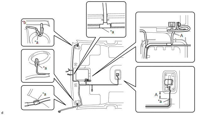
|
*a |
Aiming Tape |
*b |
Adjustment Are |
(2) Using hot-melt glue, install the No. 1 roof wire.
NOTICE:
Do not apply hot-melt glue to the position A shown in the illustration.
HINT:
Use the adjustment area to accommodate any excess length of the No. 1 roof wire.
(b) w/o EC Mirror:
(1) Align the aiming tape as shown in the illustration.

|
*a |
Aiming Tape |
*b |
Adjustment Are |
(2) Using hot-melt glue, install the No. 1 roof wire.
NOTICE:
Do not apply hot-melt glue to the position A shown in the illustration.
HINT:
Use the adjustment area to accommodate any excess length of the No. 1 roof wire.
3. INSTALL NO. 1 ROOF WIRE (w/o Vanity Light)
(a) w/ EC Mirror:
(1) Align the aiming tape as shown in the illustration.
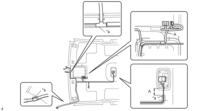
|
*a |
Aiming Tape |
- |
- |
(2) Using hot-melt glue, install the No. 1 roof wire.
NOTICE:
Do not apply hot-melt glue to the position A shown in the illustration.
(b) w/o EC Mirror:
(1) Align the aiming tape as shown in the illustration.
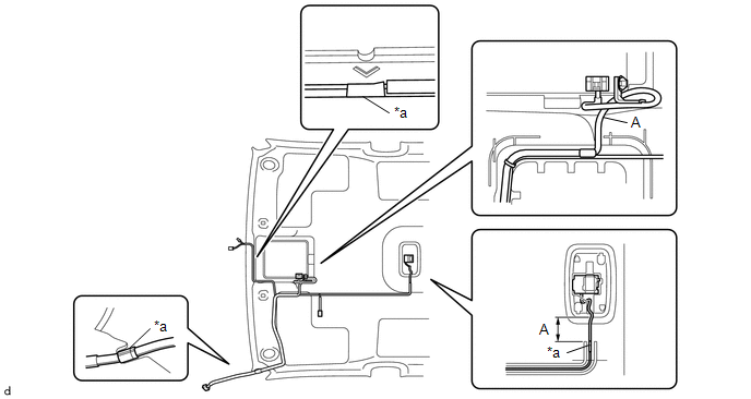
|
*a |
Aiming Tape |
- |
- |
(2) Using hot-melt glue, install the No. 1 roof wire.
NOTICE:
Do not apply hot-melt glue to the position A shown in the illustration.
4. INSTALL MICROPHONE CASE
HINT:
Use the same procedure for Double Cab.
Click here .gif)
5. INSTALL TELEPHONE MICROPHONE ASSEMBLY
Click here
 Installation
INSTALLATION
PROCEDURE
1. INSTALL ROOF HEADLINING ASSEMBLY
(a) Insert the roof headlining assembly into the vehicle from the door.
NOTICE:
Check that the corners of th ...

Other materials:
System Description
SYSTEM DESCRIPTION
1. POWER DOOR LOCK CONTROL SYSTEM DESCRIPTION
(a) The power door lock system locks/unlocks all the doors.
The main body ECU (multiplex network body ECU) receives lock/unlock request signals
from a door control switch or the driver door key lock and unlock switch. Then,
the ...
Multimedia system types
Entune Audio
Entune Audio Plus
Refer to the “NAVIGATION SYSTEM OWNER’S MANUAL”.
Entune Premium Audio
Refer to the “NAVIGATION SYSTEM OWNER’S MANUAL”.
...
Front Airbag Sensor RH Circuit Malfunction (B1610/13)
DESCRIPTION
The front airbag sensor RH consists of parts such as the diagnostic circuit and
the frontal detection sensor.
When the airbag sensor assembly receives signals from the frontal deceleration
sensor, it determines whether or not the SRS should be activated.
DTC B1610/13 is set when a ...
