Toyota Tacoma (2015-2018) Service Manual: Fender Panel Mudguard
Components
COMPONENTS
ILLUSTRATION
ILLUSTRATION
Installation
INSTALLATION
CAUTION / NOTICE / HINT
HINT:
- Use the same procedure for the RH side and LH side.
- The following procedure is for the LH side.
PROCEDURE
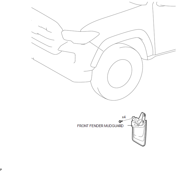
1. INSTALL FRONT FENDER MUDGUARD
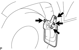
(a) Install the front fender mudguard with the 4 screws.
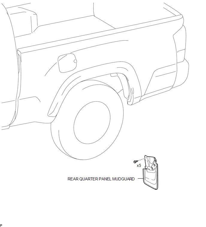
2. INSTALL REAR QUARTER PANEL MUDGUARD
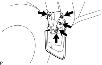
(a) Install the rear quarter panel mudguard with the 5 screws.
Removal
REMOVAL
CAUTION / NOTICE / HINT
HINT:
- Use the same procedure for the RH side and LH side.
- The following procedure is for the LH side.
PROCEDURE
1. REMOVE FRONT FENDER MUDGUARD
|
(a) Remove the 4 screws and front fender mudguard. |
|
2. REMOVE REAR QUARTER PANEL MUDGUARD
|
(a) Remove the 5 screws and rear quarter panel mudguard. |
|
 Exterior
...
 Front Bumper
...
Other materials:
Torque Converter Clutch Pressure Control Solenoid Control Circuit Open (P275613)
DESCRIPTION
Refer to the system description for DTC P27567F (See page
).
DTC No.
DTC Detection Condition
Trouble Area
SAE
P275613
Open or short is detected in shift solenoid valve SLU circuit for 1 second
or more while d ...
Problem Symptoms Table
PROBLEM SYMPTOMS TABLE
HINT:
Use the table below to help determine the cause of problem symptoms. If multiple
suspected areas are listed, the potential causes of the symptoms are listed in order
of probability in the "Suspected Area" column of the table. Check each symptom by
check ...
Components
COMPONENTS
ILLUSTRATION
*A
w/ Front Spoiler
-
-
*1
RADIATOR GRILLE
*2
FRONT NO. 1 WHEEL OPENING EXTENSION PAD
ILLUSTRATION
*A
w/o Over Fender
-
- ...
