Toyota Tacoma (2015-2018) Service Manual: Side Turn Signal Light Assembly
Components
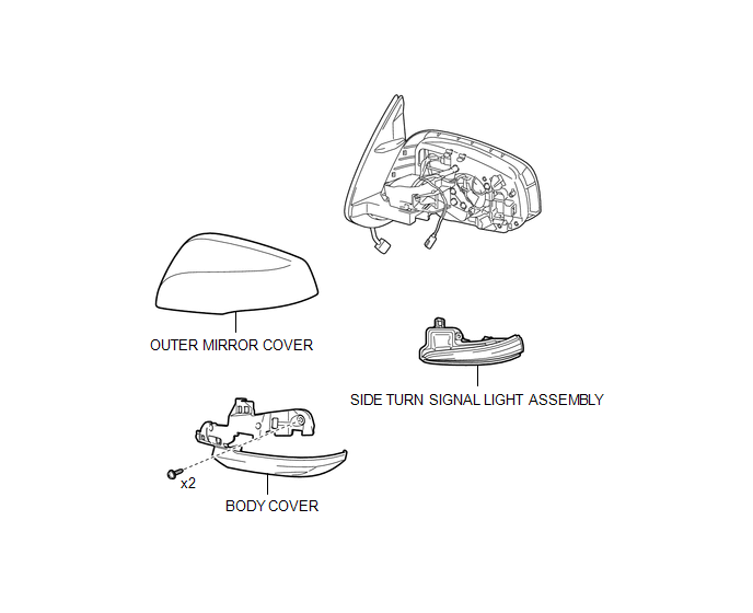
COMPONENTS
ILLUSTRATION
Removal
REMOVAL
CAUTION / NOTICE / HINT
HINT:
- Use the same procedure for both the RH and LH sides.
- The procedure described below is for the LH side.
PROCEDURE
1. REMOVE OUTER REAR VIEW MIRROR ASSEMBLY
(See page .gif) )
)
2. REMOVE OUTER MIRROR COVER
3. REMOVE SIDE TURN SIGNAL LIGHT ASSEMBLY
|
(a) Remove the 2 screws. |
|
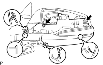
(b) Disengage the 4 claws to separate the body cover with side turn signal light assembly.
|
(c) Disengage the guide to separate the wire harness. |
|
(d) Disconnect the connector to remove the body cover with side turn signal light assembly.
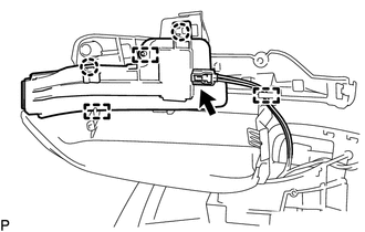
(e) Disengage the 2 claws and 2 guides to remove the side turn signal light assembly.
Inspection
INSPECTION
PROCEDURE
1. INSPECT SIDE TURN SIGNAL LIGHT ASSEMBLY LH
(a) Check the illuminates.
|
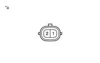
(1) Apply battery voltage to the connector and check the light illumination condition. Text in Illustration
OK:
If the result is not as specified, replace the side turn signal light assembly LH. |
|
2. INSPECT SIDE TURN SIGNAL LIGHT ASSEMBLY RH
(a) Check the illuminates.
|
(1) Apply battery voltage to the connector and check the light illumination condition. Text in Illustration
OK:
If the result is not as specified, replace the side turn signal light assembly RH. |
|
Installation
INSTALLATION
CAUTION / NOTICE / HINT
HINT:
- Use the same procedure for both the LH and RH sides.
- The procedure described below is for the LH side.
PROCEDURE
1. INSTALL SIDE TURN SIGNAL LIGHT ASSEMBLY
(a) Engage the 2 guides and 2 claws to install the side turn signal light assembly.
(b) Connect the connector.
(c) Engage the clamp to install the wire harness.
(d) Engage the 4 claws to install the body cover with side turn signal light assembly.
(e) Install the 2 screws.
2. INSTALL OUTER MIRROR COVER
.gif)
3. INSTALL OUTER REAR VIEW MIRROR ASSEMBLY
(See page )
 Room Light Assembly
Components
COMPONENTS
ILLUSTRATION
Removal
REMOVAL
PROCEDURE
1. REMOVE NO. 1 ROOM LIGHT ASSEMBLY
(a) Using a screwdriver with its tip wrapped in protective tape, disengage
...
 Stop Light Switch
Components
COMPONENTS
ILLUSTRATION
Inspection
INSPECTION
PROCEDURE
1. INSPECT STOP LIGHT SWITCH
(a) Check the resistance.
(1) Measure the resistance using an ohmmeter, and check the re ...
Other materials:
Blind Spot Monitor Slave Module Beam Axis Inspection Incomplete (C1ABC)
DESCRIPTION
This DTC is stored when a beam axis inspection has not been performed for the
blind spot monitor sensor RH.
HINT:
This DTC is always stored after replacing a blind spot monitor sensor. The purpose
of this DTC is to ensure that beam axis inspection is performed. Completing the
be ...
Components
COMPONENTS
ILLUSTRATION
*1
FUEL PUMP ASSEMBLY
*2
FUEL PUMP LIFTER ASSEMBLY
*3
FUEL PUMP LIFTER GUIDE
*4
FUEL PUMP SPACER GASKET
*5
NO. 1 FUEL PIPE SUB-ASSEMBLY
*6
...
Data List / Active Test
DATA LIST / ACTIVE TEST
READ DATA LIST
NOTICE:
In the table below, the values listed under "Normal Condition" are reference
values. Do not depend solely on these reference values when deciding whether a part
is faulty or not.
HINT:
Using the Techstream to read the Data List allows ...
