Toyota Tacoma (2015-2018) Service Manual: Terminals Of Ecu
TERMINALS OF ECU
1. CHECK TIRE PRESSURE WARNING ECU AND RECEIVER
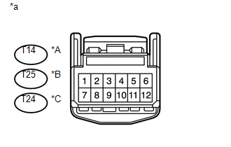
(a) Disconnect the T14 tire pressure warning ECU and receiver connector and measure the voltage and resistance on the wire harness side.
 Text in Illustration
|
*A |
w/o Wireless Door Lock System |
|
*B |
w/o Smart Key System with Wireless Door Lock System |
|
*C |
w/ Smart Key System |
|
*a |
Front view of wire harness connector (to Tire Pressure Warning ECU and Receiver) |
|
Terminal No. (Symbol) |
Wiring Color |
Terminal Description |
Condition |
Specified Condition |
|---|---|---|---|---|
|
T14-1 (IG) - T14-12 (GND) |
LG - W-B |
IG power source |
Ignition switch ON |
10 to 16 V |
|
T14-12 (GND) - Body ground |
W-B - Body ground |
Ground |
Always |
Below 1 Ω |
|
Terminal No. (Symbol) |
Wiring Color |
Terminal Description |
Condition |
Specified Condition |
|---|---|---|---|---|
|
T25-1 (IG) - T25-12 (GND) |
LG - W-B |
IG power source |
Ignition switch ON |
10 to 16 V |
|
T25-7 (+B) - T25-12 (GND |
BE - W-B |
Power supply (from battery) |
Always |
10 to 16 V |
|
T25-12 (GND) - Body ground |
W-B - Body ground |
Ground |
Always |
Below 1 Ω |
|
Terminal No. (Symbol) |
Wiring Color |
Terminal Description |
Condition |
Specified Condition |
|---|---|---|---|---|
|
T24-1 (IG) - T24-12 (GND) |
LG - W-B |
IG power source |
Ignition switch ON |
10 to 16 V |
|
T24-7 (+B) - T24-12 (GND) |
BE - W-B |
Power supply (from battery) |
Always |
10 to 16 V |
|
T24-12 (GND) - Body ground*1 |
W-B - Body ground |
Ground |
Always |
Below 1 Ω |
(b) Connect the T14*1, T25*2, T24*3 tire pressure warning ECU and receiver connector.
(c) Measure the voltage and resistance according to the value(s) in the table below. If the result is not as specified, the ECU may be malfunctioning.
HINT:
Measure the values on the wire harness side while the connector is connected.

|
Terminal No. (Symbol) |
Wiring Color |
Terminal Description |
Condition |
Specified Condition |
|---|---|---|---|---|
|
T14-3 (CLSW) - T14-12 (GND)*1 T25-3 (CLSW) - T25-12 (GND)*2 T24-3 (CLSW) - T24-12 (GND)*3 |
R - W-B |
Tire pressure warning reset switch |
|
Below 1.5 V |
|
8 to 15 V |
|||
|
T14-4 (RDA) - T14-12 (GND)*1 T25-4 (RDA) - T25-12 (GND)*2 T24-4 (RDA) - T24-12 (GND)*3 |
B - W-B |
Output signals |
Ignition switch ON |
Pulse generation (see waveform 1) |
|
T14-5 (PRG) - T14-12 (GND)*1 T25-5 (PRG) - T25-12 (GND)*2 T24-5 (PRG) - T24-12 (GND)*3 |
GR - W-B |
Input signals |
Ignition switch ON |
Pulse generation (see waveform 1) |
- *1: w/o Wireless Door Lock System
- *2: w/o Smart Key System with Wireless Door Lock System
- *3: w/ Smart Key System
(d) Using an oscilloscope, check waveform 1.
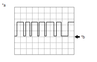
Waveform 1:
|
Item |
Contents |
|---|---|
|
Terminal |
T14-4 (RDA) - T14-12 (GND)*1 T25-4 (RDA) - T25-12 (GND)*2 T24-4 (RDA) - T24-12 (GND)*3 T14-5 (PRG) - T14-12 (GND)*1 T25-5 (PRG) - T25-12 (GND)*2 T24-5 (PRG) - T24-12 (GND)*3 |
|
Tool setting |
5 V/DIV., 5 ms./DIV. |
|
Vehicle condition |
Ignition switch ON |
- *1: w/o Wireless Door Lock System
- *2: w/o Smart Key System with Wireless Door Lock System
- *3: w/ Smart Key System
|
*a |
Example |
|
*b |
GND |
HINT:
The waveform shown in the illustration is an example. If the tester displays a waveform that alternates between high and low, where high is a voltage that is between the IG power source voltage and a voltage 2.2 V lower than the IG power source voltage, and where low is a voltage of between 0 and 1.2 V, the ECU can be judged normal.
 Problem Symptoms Table
PROBLEM SYMPTOMS TABLE
HINT:
Use the table below to help determine the cause of problem symptoms.
If multiple suspected areas are listed, the potential causes of the symptoms
are lis ...
 Test Mode Procedure
TEST MODE PROCEDURE
1. TEST MODE (SIGNAL CHECK MODE) PROCEDURE
HINT:
When entering test mode (signal check mode), the tire pressure warning
ECU and receiver stores all the test mode (si ...
Other materials:
Amplifier Box Speaker Assembly
Components
COMPONENTS
ILLUSTRATION
ILLUSTRATION
Removal
REMOVAL
PROCEDURE
1. PRECAUTION
NOTICE:
After turning the ignition switch off, waiting time may be required before disconnecting
the cable from the negative (-) battery terminal. Therefore, make sure to read the
disconnecti ...
Data List / Active Test
DATA LIST / ACTIVE TEST
1. DATA LIST
HINT:
Using the Techstream to read the Data List allows the values or states of switches,
sensors, actuators and other items to be read without removing any parts. This non-intrusive
inspection can be very useful because intermittent conditions or signals ...
Engine
General Maintenance
GENERAL MAINTENANCE
CAUTION / NOTICE / HINT
HINT:
Inspect these items when the engine is cold.
PROCEDURE
1. REPLACE CHAIN SUB-ASSEMBLY
HINT:
2TR-FE: See page
2GR-FKS: See page
2. INSPECT DRIVE BELT
HINT:
2TR-FE: See page
2GR-FKS: ...
