Toyota Tacoma (2015-2018) Service Manual: Room Light Assembly
Components
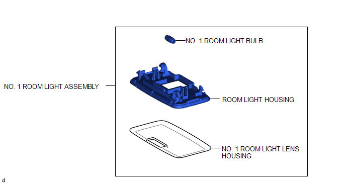
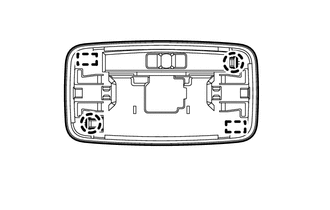
COMPONENTS
ILLUSTRATION
Removal
REMOVAL
PROCEDURE
1. REMOVE NO. 1 ROOM LIGHT ASSEMBLY
|
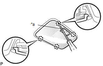
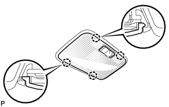
(a) Using a screwdriver with its tip wrapped in protective tape, disengage the 4 claws to remove the No. 1 room light lens. Text in Illustration
|
|
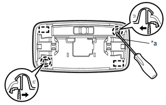
(b) Using a screwdriver with its tip wrapped in protective tape, disengage the 2 claws and 2 guides to separate the No. 1 room light housing as shown in the illustration.
 Text in Illustration
|
*a |
Protective Tape |
.png) |
Push |
(c) Disengage the guide to separate the wire harness.
|
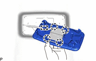
(d) Disengage the 4 claws to separate the No. 1 room light housing from the room light switch base. |
|
2. REMOVE NO. 1 ROOM LIGHT BULB
(a) Remove the No. 1 room light bulb.
Installation
INSTALLATION
PROCEDURE
1. INSTALL NO. 1 ROOM LIGHT BULB
(a) Install the No. 1 room light bulb.
2. INSTALL NO. 1 ROOM LIGHT ASSEMBLY
(a) Engage the 4 claws to install the No. 1 room light housing to the room light switch base.
(b) Engage the guide to install the wire harness.
|
(c) Engage the 2 guides and 2 claws to install the No. 1 room light housing. |
|
|
(d) Engage the 4 claws to install the No. 1 room light lens. |
|
 Rear Door Courtesy Switch
Inspection
INSPECTION
PROCEDURE
1. INSPECT REAR DOOR COURTESY SWITCH
(a) Check the resistance.
(1) Measure the resistance using an ohmmeter, and check the results in accordance
with the value ...
 Side Turn Signal Light Assembly
Components
COMPONENTS
ILLUSTRATION
Removal
REMOVAL
CAUTION / NOTICE / HINT
HINT:
Use the same procedure for both the RH and LH sides.
The procedure described below is for the ...
Other materials:
On-vehicle Inspection
ON-VEHICLE INSPECTION
PROCEDURE
1. INSPECT LOWER NO. 1 INSTRUMENT PANEL AIRBAG ASSEMBLY (for Vehicle not Involved
in Collision)
(a) Perform a diagnostic system check (See page
).
(b) With the lower No. 1 instrument panel airbag assembly ...
Inspection
INSPECTION
PROCEDURE
1. INSPECT REAR NO. 2 POWER WINDOW REGULATOR SWITCH ASSEMBLY
*a
Component without harness connected
(Rear No. 2 Power Window Regulator Switch Assembly)
*b
Pull (Close)
*c
Push (Open)
...
Check For Intermittent Problems
CHECK FOR INTERMITTENT PROBLEMS
1. DESCRIPTION
HINT:
A momentary interruption (open circuit) in the connectors and/or wire harness
between the sensors and ECUs can be detected through the ECU data monitor function
of the Techstream.
(a) Turn the ignition switch off.
(b) Connect the Techstre ...
