Toyota Tacoma (2015-2018) Service Manual: Components
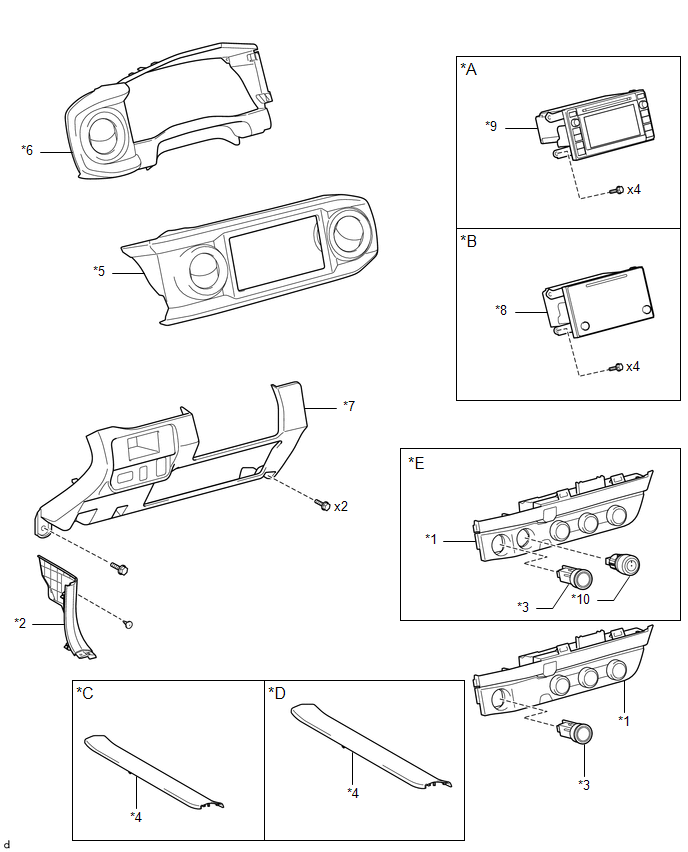
COMPONENTS
ILLUSTRATION
|
*A |
w/o Navigation System |
*B |
w/ Navigation System |
|
*C |
for Double Cab |
*D |
for Acces Cab |
|
*E |
for 4WD |
- |
- |
|
*1 |
AIR CONDITIONING CONTROL ASSEMBLY |
*2 |
COWL SIDE TRIM BOARD LH |
|
*3 |
ENGINE SWITCH |
*4 |
FRONT DOOR SCUFF PLATE LH |
|
*5 |
INSTRUMENT CLUSTER CENTER FINISH PANEL SUB-ASSEMBLY |
*6 |
INSTRUMENT CLUSTER FINISH PANEL ASSEMBLY |
|
*7 |
INSTRUMENT PANEL LOWER FINISH PANEL SUB-ASSEMBLY |
*8 |
NAVIGATION RECEIVER ASSEMBLY WITH BRACKET |
|
*9 |
RADIO AND DISPLAY RECEIVER ASSEMBLY WITH BRACKET |
*10 |
TRANSFER POSITION SWITCH |

 Inspection
INSPECTION
PROCEDURE
1. INSPECT AIR CONDITIONING CONTROL ASSEMBLY
(a) Check the blower switch resistance.
(1) Measure the resistance according to the value(s) in the table below.
T ...
Other materials:
Low Power Supply Voltage Malfunction (C1241)
DESCRIPTION
If a malfunction is detected in the power supply circuit, the skid control ECU
(brake actuator assembly) stores this DTC and the fail-safe function prohibits ABS
operation.
This DTC is stored when the +BS terminal voltage deviates from the DTC detection
condition due to a malfunc ...
Cargo Light Switch
Components
COMPONENTS
ILLUSTRATION
Inspection
INSPECTION
PROCEDURE
1. INSPECT DECK LIGHT SWITCH ASSEMBLY
(a) Check the resistance.
(1) Measure the resistance according to the value(s) in the table below.
Text in Illustration
*a
Compone ...
Removal
REMOVAL
PROCEDURE
1. REMOVE REAR SEAT CUSHION ASSEMBLY
2. REMOVE NO. 4 ROOM PARTITION COVER LH
3. REMOVE NO. 4 ROOM PARTITION COVER RH
4. REMOVE NO. 3 ROOM PARTITION COVER
5. REMOVE BACK PANEL GARNISH HOLE PLUG
6. REMOVE BACK PANEL TRIM
7. REMOVE FRONT DOOR SCUFF PLATE ...
