Toyota Tacoma (2015-2018) Service Manual: Short to +B in Outer Mirror Indicator(Slave) (C1AB1)
DESCRIPTION
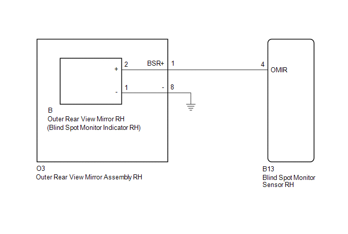
This DTC is stored when the blind spot monitor sensor RH detects a +B short in the blind spot monitor indicator RH.
|
DTC Code |
DTC Detection Condition |
Trouble Area |
|---|---|---|
|
C1AB1 |
With the blind spot monitor main switch assembly (warning canceling switch assembly) on, the voltage applied to the indicator is high for a certain amount of time even though the blind spot monitor sensor is not outputting voltage to the indicator. |
|
WIRING DIAGRAM
CAUTION / NOTICE / HINT
NOTICE:
When checking for DTCs, make sure that the blind spot monitor main switch assembly (warning canceling switch assembly) is on.
PROCEDURE
|
1. |
CHECK DTC |
(a) Clear the DTCs (See page .gif) ).
).
(b) Recheck for DTCs and check if the same DTC is output again (See page
).
OK:
No DTCs are output.
| OK | .gif) |
USE SIMULATION METHOD TO CHECK |
|
.gif)
|
2. |
CHECK HARNESS AND CONNECTOR (OUTER REAR VIEW MIRROR INDICATOR RH CIRCUIT) |
|
(a) Disconnect the blind spot monitor sensor RH connector. |
|
.png)
(b) Measure the voltage according to the value(s) in the table below.
Standard Voltage:
|
Tester Connection |
Switch Condition |
Specified Condition |
|---|---|---|
|
B13-4 (OMIR) - Body ground |
Ignition switch ON |
Below 1 V |
|
*a |
Front view of wire harness connector (to Blind Spot Monitor Sensor RH) |
| OK | |
REPLACE BLIND SPOT MONITOR SENSOR RH |
|
|
3. |
CHECK HARNESS AND CONNECTOR (BLIND SPOT MONITOR SENSOR RH - OUTER REAR VIEW MIRROR ASSEMBLY RH) |
|
(a) Disconnect the blind spot monitor sensor RH connector. |
|
(b) Disconnect the O3 outer rear view mirror assembly RH connector.
(c) Measure the voltage according to the value(s) in the table below.
Standard Voltage:
|
Tester Connection |
Switch Condition |
Specified Condition |
|---|---|---|
|
B13-4 (OMIR) - Body ground |
Ignition switch ON |
Below 1 V |
|
*a |
Front view of wire harness connector (to Blind Spot Monitor Sensor RH) |
| NG | |
REPAIR OR REPLACE HARNESS OR CONNECTOR |
|
|
4. |
CHECK HARNESS AND CONNECTOR (BLIND SPOT MONITOR SENSOR RH - OUTER REAR VIEW MIRROR RH) |
(a) Reconnect the O3 outer rear view mirror assembly RH connector.
|
(b) Disconnect the blind spot monitor sensor RH connector. |
|
(c) Disconnect the B outer rear view mirror RH connector.
(d) Measure the voltage according to the value(s) in the table below.
Standard Voltage:
|
Tester Connection |
Switch Condition |
Specified Condition |
|---|---|---|
|
B13-4 (OMIR) - Body ground |
Ignition switch ON |
Below 1 V |
|
*a |
Front view of wire harness connector (to Blind Spot Monitor Sensor RH) |
| OK | |
REPLACE OUTER REAR VIEW MIRROR RH |
| NG | |
REPLACE OUTER REAR VIEW MIRROR ASSEMBLY RH |
 Short to GND in Outer Mirror Indicator(Slave) (C1AB3)
DESCRIPTION
This DTC is stored when the blind spot monitor sensor RH detects a ground short
in the blind spot monitor indicator RH.
DTC Code
DTC Detection Condition
...
 Vehicle Speed Sensor (C1A45)
DESCRIPTION
The blind spot monitor sensor receives vehicle speed signals from the skid control
ECU (brake actuator assembly) via CAN communication.
DTC Code
DTC Detection Con ...
Other materials:
Transmission Range Sensor "A" Circuit Open (P070513,P070562)
DESCRIPTION
The park/neutral position switch detects the shift lever position and sends signals
to the ECM.
DTC No.
DTC Detection Condition
Trouble Area
SAE
P070513
All of the following signals are OFF simultaneously for 60 ...
Installation
INSTALLATION
PROCEDURE
1. INSTALL CHARCOAL CANISTER LEAK DETECTION PUMP SUB-ASSEMBLY
(a) Engage the 2 claws to install a new charcoal canister leak detection
pump sub-assembly to the charcoal canister assembly.
NOTICE:
Do not allow foreign matter such as grease, ...
Diagnosis System
DIAGNOSIS SYSTEM
DIAGNOSIS FUNCTION
(a) The diagnosis function turns off the cruise control indicator, illuminates
the master warning light and displays a warning message when a malfunction is detected.
When a malfunction is detected in the dynamic radar cruise control system, DTCs
are store ...
