Toyota Tacoma (2015-2018) Service Manual: Short to GND in Outer Mirror Indicator(Slave) (C1AB3)
DESCRIPTION
This DTC is stored when the blind spot monitor sensor RH detects a ground short in the blind spot monitor indicator RH.
|
DTC Code |
DTC Detection Condition |
Trouble Area |
|---|---|---|
|
C1AB3 |
With the blind spot monitor main switch assembly (warning canceling switch assembly) on, the voltage output from the blind spot monitor sensor to the indicator is low for a certain amount of time. |
|
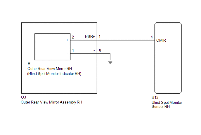
WIRING DIAGRAM
CAUTION / NOTICE / HINT
NOTICE:
When checking for DTCs, make sure that the blind spot monitor main switch assembly (warning canceling switch assembly) is on.
PROCEDURE
|
1. |
CHECK DTC |
(a) Clear the DTCs (See page .gif) ).
).
(b) Recheck for DTCs and check if the same DTC is output again (See page
).
OK:
No DTCs are output.
| OK | .gif) |
USE SIMULATION METHOD TO CHECK |
|
.gif)
|
2. |
CHECK HARNESS AND CONNECTOR (OUTER REAR VIEW MIRROR ASSEMBLY RH - BLIND SPOT MONITOR SENSOR RH) |
(a) Disconnect the O3 outer rear view mirror assembly RH connector.
(b) Disconnect the B13 blind spot monitor sensor RH connector.
(c) Measure the resistance according to the value(s) in the table below.
Standard Resistance:
|
Tester Connection |
Condition |
Specified Condition |
|---|---|---|
|
O3-1 (BSR+) - Body ground |
Always |
10 kΩ or higher |
| NG | |
REPAIR OR REPLACE HARNESS OR CONNECTOR |
|
|
3. |
CHECK HARNESS AND CONNECTOR (BLIND SPOT MONITOR SENSOR RH - OUTER REAR VIEW MIRROR RH) |
(a) Reconnect the O3 outer rear view mirror assembly RH connector.
|
(b) Disconnect the blind spot monitor sensor RH connector. |
|
(c) Disconnect the B outer rear view mirror RH connector.
(d) Measure the resistance according to the value(s) in the table below.
Standard Resistance:
|
Tester Connection |
Condition |
Specified Condition |
|---|---|---|
|
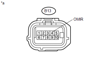
B13-4 (OMIR) - Body ground |
Always |
10 kΩ or higher |
|
*a |
Front view of wire harness connector (to Blind Spot Monitor Sensor RH) |
| NG | |
REPLACE OUTER REAR VIEW MIRROR ASSEMBLY RH |
|
|
4. |
CHECK OUTER REAR VIEW MIRROR RH |
(a) Replace the outer rear view mirror RH with a new or normally functioning
one (See page ).
(b) Clear the DTCs (See page ).
(c) Recheck for DTCs and check if the same DTC is output again (See page
).
OK:
No DTCs are output.
| OK | |
END (OUTER REAR VIEW MIRROR RH WAS DEFECTIVE) |
| NG | |
REPLACE BLIND SPOT MONITOR SENSOR RH |
 Short to GND in Outer Mirror Indicator(Master) (C1AB2)
DESCRIPTION
This DTC is stored when the blind spot monitor sensor LH detects a ground short
in the blind spot monitor indicator LH.
DTC Code
DTC Detection Condition
...
 Short to +B in Outer Mirror Indicator(Slave) (C1AB1)
DESCRIPTION
This DTC is stored when the blind spot monitor sensor RH detects a +B short in
the blind spot monitor indicator RH.
DTC Code
DTC Detection Condition
Tr ...
Other materials:
Freeze Frame Data
FREEZE FRAME DATA
DESCRIPTION
(a) When a pre-collision system DTC is stored, the millimeter wave radar sensor
assembly stores the current vehicle (ECU or sensor) state as Freeze Frame Data.
CHECK FREEZE FRAME DATA
(a) Connect the Techstream to the DLC3.
(b) Turn the ignition switch to ON.
(c ...
Installation
INSTALLATION
PROCEDURE
1. INSTALL WATER INLET WITH THERMOSTAT SUB-ASSEMBLY
(a) Install a new gasket to the water inlet with thermostat sub-assembly.
(b) Install the water inlet with thermostat sub-assembly to the timing chain
cover assembly with the 2 bolts and nut.
Torque:
10 N·m {102 kgf ...
Removal
REMOVAL
PROCEDURE
1. REMOVE RADIATOR GRILLE
(a) w/ Toyota Safety Sense P
(1) Disconnect the connector.
(2) Disengage the clamp.
(b) Put protective tape around the radiator grille.
...
