Toyota Tacoma (2015-2018) Service Manual: Installation
INSTALLATION
PROCEDURE
1. REMOVE MONOLITHIC CONVERTER PROTECTOR
(a) Install the upper monolithic converter protector and lower monolithic converter protector with the 2 bolts and 2 nuts.
Torque:
11 N·m {107 kgf·cm, 8 ft·lbf}
|
(b) Install the clamp with the bolt as shown in the illustration. Text in Illustration
Torque: 11 N·m {107 kgf·cm, 8 ft·lbf} |
|
2. INSTALL FRONT EXHAUST PIPE ASSEMBLY
(a) Install a new gasket to the front exhaust pipe assembly.
(b) Install the front exhaust pipe assembly to the exhaust manifold sub-assembly RH with the 2 new nuts.
Torque:
54 N·m {554 kgf·cm, 40 ft·lbf}
3. INSTALL FRONT NO. 2 EXHAUST PIPE ASSEMBLY
(a) Install a new gasket to the front No. 2 exhaust pipe assembly.
(b) Connect the front No. 2 exhaust pipe assembly to the exhaust pipe support.
(c) Install the front No. 2 exhaust pipe assembly to the exhaust manifold LH with the 2 new nuts.
Torque:
54 N·m {554 kgf·cm, 40 ft·lbf}
4. INSTALL EXHAUST PIPE STOPPER BRACKET (for 4WD)
(a) Install the exhaust pipe stopper bracket with the 2 bolts.
Torque:
19 N·m {194 kgf·cm, 14 ft·lbf}
5. INSTALL CENTER NO. 2 FLOOR HEAT INSULATOR SUB-ASSEMBLY (for 4WD)
(a) Install the center No. 2 floor heat insulator sub-assembly with the 3 nuts.
Torque:
5.5 N·m {56 kgf·cm, 49 in·lbf}
6. INSTALL CENTER EXHAUST PIPE ASSEMBLY
(a) Temporarily install a new exhaust pipe gasket to the front exhaust pipe assembly.
|
(b) Using a plastic hammer and wooden block, tap in the gasket until its surface is flush with the front exhaust pipe assembly. Text in Illustration
NOTICE:
|
|
(c) Connect the center exhaust pipe assembly to the exhaust pipe support.
(d) Install a new gasket to the front No. 2 exhaust pipe assembly.
(e) Install the center exhaust pipe assembly to the front No. 2 exhaust pipe assembly with the 2 bolts.
Torque:
48 N·m {489 kgf·cm, 35 ft·lbf}
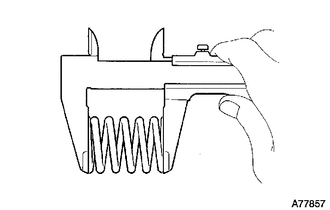
(f) Check the free length.
|
(1) Using a vernier caliper, measure the free length of the compression spring. Free Length of Compression Spring:
If the free length is less than the minimum, replace the compression spring. |
|
|
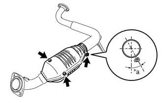
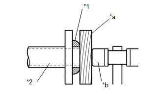
(g) Install the center exhaust pipe to the front exhaust pipe assembly with the 2 compression springs and 2 bolts. Text in Illustration
Torque: 43 N·m {438 kgf·cm, 32 ft·lbf} HINT: After the installation, check that the gaps between the flanges of the front exhaust pipe assembly and center exhaust pipe assembly are consistent front-to-rear and left-to-right. |
|
.png)
7. INSTALL TAIL EXHAUST PIPE ASSEMBLY
(a) Connect the tail exhaust pipe assembly to the 4 exhaust pipe supports.
(b) Install a new gasket to the center exhaust pipe assembly.
(c) Install the tail exhaust pipe assembly to the center exhaust pipe assembly with the 2 bolts.
Torque:
48 N·m {489 kgf·cm, 35 ft·lbf}
8. INSTALL HEATED OXYGEN SENSOR
Click here .gif)
9. CONNECT CABLE TO NEGATIVE BATTERY TERMINAL
Torque:
5.4 N·m {55 kgf·cm, 48 in·lbf}
NOTICE:
When disconnecting the cable, some systems need to be initialized after the cable is reconnected.
Click here
10. INSPECT FOR EXHAUST GAS LEAK
(a) Perform Inspection After Repair after repairing an exhaust gas leak.
Click here
 Removal
REMOVAL
PROCEDURE
1. PRECAUTION
NOTICE:
After turning the ignition switch off, waiting time may be required before disconnecting
the cable from the negative (-) battery terminal. Therefore, make ...
 2gr-fks Fuel
...
Other materials:
Removal
REMOVAL
CAUTION / NOTICE / HINT
NOTICE:
If one of the camshaft timing gear bolts is already removed, do not remove any
other camshaft timing gear bolts.
PROCEDURE
1. REMOVE NO. 2 ENGINE UNDER COVER SUB-ASSEMBLY (w/ Off Road Package)
2. REMOVE NO. 1 ENGINE UNDER COVER SUB-ASSEMBLY
3. REMOVE ...
Image from Camera for Rear View Monitor is Abnormal
DESCRIPTION
The display signal of the rear television camera assembly is transmitted to the
radio and display receiver assembly*1 or navigation receiver assembly*2.
*1: w/o Navigation System
*2: w/ Navigation System
WIRING DIAGRAM
PROCEDURE
1.
CONFIRM ...
Components
COMPONENTS
ILLUSTRATION
ILLUSTRATION
ILLUSTRATION
ILLUSTRATION
ILLUSTRATION
*A
w/ Seat Heater System
-
-
*1
FRONT SEAT CUSHION HEATER ASSEMBLY
*2
FRONT SEATBACK HEATER ASSEMBLY
...
