Toyota Tacoma (2015-2018) Service Manual: Electrical Key Oscillator(for Rear Floor)
Components
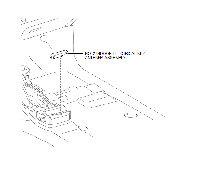
COMPONENTS
ILLUSTRATION
Installation
INSTALLATION
PROCEDURE
1. INSTALL NO. 2 INDOOR ELECTRICAL KEY ANTENNA ASSEMBLY
(a) Engage the clamp to install the No. 2 indoor electrical key antenna assembly.
(b) Connect the connector.
2. INSTALL REAR CONSOLE BOX ASSEMBLY
(See page .gif) )
)
Removal
REMOVAL
PROCEDURE
1. REMOVE REAR CONSOLE BOX ASSEMBLY
(See page .gif) )
)
2. REMOVE NO. 2 INDOOR ELECTRICAL KEY ANTENNA ASSEMBLY
|
(a) Disconnect the connector. |
|
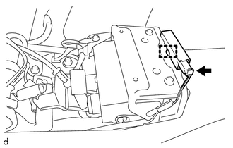
(b) Using a clip remover, disengage the clamp to remove the No. 2 indoor electrical key antenna assembly.
 Electrical Key Oscillator(for Front Floor)
Components
COMPONENTS
ILLUSTRATION
Installation
INSTALLATION
PROCEDURE
1. INSTALL NO. 1 INDOOR ELECTRICAL KEY ANTENNA ASSEMBLY
(a) Engage the clamp to install the No. 1 indoor electrical ...

Other materials:
Replacement
REPLACEMENT
PROCEDURE
1. RECOVER REFRIGERANT FROM REFRIGERATION SYSTEM
(a) Start the engine.
(b) Operate the cooler compressor under the conditions shown below:
Item
Condition
Engine Speed
Idling
Operating Time
3 minu ...
Pattern Select Switch
Components
COMPONENTS
ILLUSTRATION
Removal
REMOVAL
PROCEDURE
1. REMOVE INSTRUMENT PANEL LOWER CENTER FINISH PANEL
(See page )
2. REMOVE PATTERN SELECT SWITCH ASSEMBLY
(a) Detach the 2 claws to remove the pattern select switch assembly from
the instrument panel lower c ...
Removal
REMOVAL
PROCEDURE
1. REMOVE FRONT CONSOLE BOX
(See page )
2. DISCONNECT TRANSMISSION CONTROL CABLE ASSEMBLY
(a) Move the shift lever to N.
(b) Disconnect the end of the transmission control cable assembly from the transmission
floor shift assembly.
Text in Illustration
...
