Toyota Tacoma (2015-2018) Service Manual: Seat Belt Buckle Switch LH Circuit Malfunction (B1656/38)
DESCRIPTION
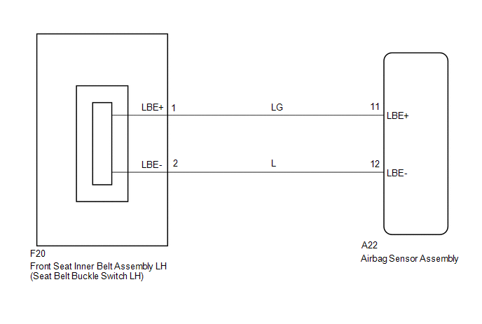
The seat belt buckle switch LH circuit consists of the airbag sensor assembly and the front seat inner belt assembly LH (seat belt buckle switch LH).
DTC B1655/37 is stored when a malfunction is detected in the seat belt buckle switch LH circuit.
|
DTC No. |
DTC Detection Condition |
Trouble Area |
|---|---|---|
|
B1655/37 |
|
|
WIRING DIAGRAM
CAUTION / NOTICE / HINT
NOTICE:
After turning the ignition switch off, waiting time may be required before disconnecting
the cable from the negative (-) battery terminal. Therefore, make sure to read the
disconnecting the cable from the negative (-) battery terminal notices before proceeding
with work (See page .gif) ).
).
PROCEDURE
|
1. |
CHECK CONNECTION OF CONNECTORS |
(a) Turn the ignition switch off.
(b) Disconnect the negative (-) terminal cable from the battery, and wait for at least 90 seconds.
(c) Check that the connectors are properly connected to the airbag sensor assembly and the seat position airbag sensor.
OK:
The connectors are properly connected.
| NG | .gif) |
CONNECT CONNECTORS |
|
.gif)
|
2. |
CHECK CONNECTORS |
(a) Disconnect the connector from the airbag sensor assembly.
(b) Disconnect the connector from the front seat inner belt assembly LH.
(c) Check that the connectors (on the airbag sensor assembly side and front seat
inner belt assembly LH side) are not damaged (See page
).
OK:
The connectors are not deformed or damaged.
|
Condition |
Proceed to |
|---|---|
|
Normal |
A |
|
Abnormal |
B |
| B | |
REPLACE HARNESS OR CONNECTOR |
|
|
3. |
CHECK NO. 2 FLOOR WIRE (AIRBAG SENSOR ASSEMBLY - FRONT SEAT INNER BELT ASSEMBLY LH) |
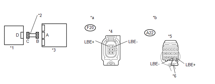 Text in Illustration
|
*1 |
Front Seat Inner Belt Assembly LH |
*2 |
No. 2 Floor Wire |
|
*3 |
Airbag Sensor Assembly |
*4 |
Connector C |
|
*5 |
Connector B |
*6 |
Service Wire |
|
*a |
Front view of wire harness connector (to Front Seat Inner Belt Assembly LH) |
*b |
Front view of wire harness connector (to Airbag Sensor Assembly) |
(a) Connect the negative (-) terminal cable to the battery, and wait for at least 2 seconds.
(b) Turn the ignition switch to ON.
(c) Measure the voltage according to the value(s) in the table below.
Standard Voltage:
|
Tester Connection |
Switch Condition |
Specified Condition |
|---|---|---|
|
F20-1 (LBE+) - Body ground |
Ignition switch ON |
Below 1 V |
|
F20-2 (LBE-) - Body ground |
Ignition switch ON |
Below 1 V |
(d) Turn the ignition switch off.
(e) Disconnect the cable from the negative (-) battery terminal, and wait for at least 90 seconds.
(f) Using a service wire, connect terminals 11 (LBE+) and 12 (LBE-) of connector B.
NOTICE:
Do not forcibly insert the service wire into the terminals of the connector when connecting the wire.
(g) Measure the resistance according to the value(s) in the table below.
Standard Resistance:
|
Tester Connection |
Condition |
Specified Condition |
|---|---|---|
|
F20-1 (LBE+) - F20-2 (LBE-) |
Always |
Below 1 Ω |
(h) Disconnect the service wire from connector B.
(i) Measure the resistance according to the value(s) in the table below.
Standard Resistance:
|
Tester Connection |
Condition |
Specified Condition |
|---|---|---|
|
F20-1 (LBE+) - F20-2 (LBE-) |
Always |
1 MΩ or Higher |
|
F20-1 (LBE+) - Body ground |
Always |
1 MΩ or Higher |
|
F20-2 (LBE-) - Body ground |
Always |
1 MΩ or Higher |
| NG | |
REPLACE NO. 2 FLOOR WIRE |
|
|
4. |
CHECK FRONT SEAT INNER BELT ASSEMBLY LH |
(a) Connect the connectors to the airbag sensor assembly.
(b) Connect the connector to the front seat inner belt assembly LH.
(c) Connect the negative (-) terminal cable to the battery, and wait for at least 2 seconds.
(d) Turn the ignition switch to ON, and wait for at least 60 seconds.
(e) Clear any DTCs stored in the memory (See page
).
(f) Turn the ignition switch off.
(g) Turn the ignition switch to ON, and wait for at least 60 seconds.
(h) Check for DTCs (See page ).
OK:
DTC B1655/37 is not output.
HINT:
DTCs other than B1655/37 may be output at this time, but they are not related to this check.
| OK | |
REPLACE USE SIMULATION METHOD TO CHECK |
|
|
5. |
CHECK FRONT SEAT INNER BELT ASSEMBLY LH |
(a) Turn the ignition switch off.
(b) Disconnect the cable from the negative (-) battery terminal, and wait for at least 90 seconds.
(c) Replace the front seat inner belt assembly (See page
).
HINT:
Perform the inspection using parts from a normal vehicle when possible.
|
|
6. |
CHECK AIRBAG SENSOR ASSEMBLY |
(a) Connect the negative (-) terminal cable to the battery, and wait for at least 2 seconds.
(b) Turn the ignition switch to ON, and wait for at least 60 seconds.
(c) Clear the DTCs (See page ).
(d) Turn the ignition switch off.
(e) Turn the ignition switch to ON, and wait for at least 60 seconds.
(f) Check for DTCs (See page ).
OK:
DTC B1655/37 is not output.
HINT:
DTCs other than B1655/37 may be output at this time, but they are not related to this check.
| OK | |
END |
| NG | |
REPLACE AIRBAG SENSOR ASSEMBLY |
 Short in Driver Side Squib 2nd Step Circuit (B1810/53-B1813/53)
DESCRIPTION
The driver side squib 2nd step circuit consists of the airbag sensor assembly,
the spiral cable with sensor sub-assembly and the horn button assembly.
The circuit signals the SRS to de ...
 Occupant Classification System Malfunction (B1650/32)
DESCRIPTION
The occupant classification system circuit consists of the airbag sensor assembly
and the occupant classification system.
When the airbag sensor assembly receives signals from the occu ...
Other materials:
Installation
INSTALLATION
CAUTION / NOTICE / HINT
HINT:
Perform "Inspection After Repairs" after replacing the engine assembly, cylinder
head sub-assembly, camshaft, No. 2 camshaft, No. 3 camshaft sub-assembly, No. 4
camshaft sub-assembly, camshaft timing gear assembly, camshaft timing exhaust g ...
Parts Location
PARTS LOCATION
ILLUSTRATION
*A
for Automatic Transmission
-
-
*1
FRONT SPEED SENSOR LH
*2
FRONT SPEED SENSOR RH
*3
FRONT AXLE WITH ABS ROTOR BEARING ASSEMBLY LH
- FRONT SP ...
Disassembly
DISASSEMBLY
CAUTION / NOTICE / HINT
HINT:
The procedure described below is for the LH side. Use the same procedure for
both the LH and RH sides, unless otherwise specified.
PROCEDURE
1. REMOVE REAR SEATBACK COVER
(a) Remove the 2 screws.
...
