Toyota Tacoma (2015-2018) Service Manual: Occupant Classification System Malfunction (B1650/32)
DESCRIPTION
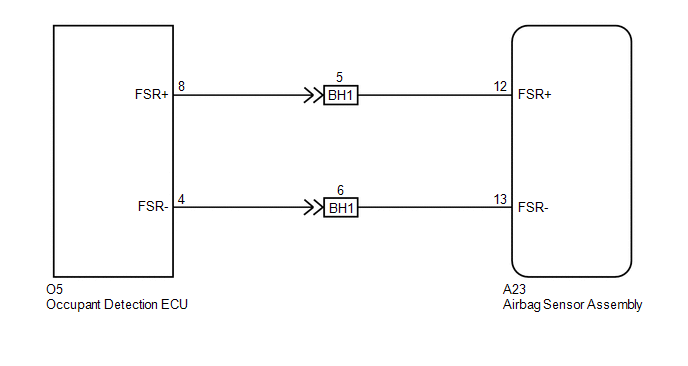
The occupant classification system circuit consists of the airbag sensor assembly and the occupant classification system.
When the airbag sensor assembly receives signals from the occupant detection ECU, it determines whether or not the instrument panel passenger without door airbag assembly, front seat airbag assembly RH and seat belt pretensioner RH should be operated.
DTC B1650/32 is set when a malfunction is detected in the occupant classification system circuit.
|
DTC No. |
DTC Detecting Conditions |
Trouble Areas |
|---|---|---|
|
B1650/32 |
|
|
WIRING DIAGRAM
CAUTION / NOTICE / HINT
NOTICE:
After turning the ignition switch off, waiting time may be required before disconnecting
the cable from the negative (-) battery terminal. Therefore, make sure to read the
disconnecting the cable from the negative (-) battery terminal notices before proceeding
with work (See page .gif) ).
).
PROCEDURE
|
1. |
CHECK DTC (AIRBAG SENSOR ASSEMBLY) |
(a) Turn the ignition switch to ON.
(b) Clear any DTCs stored in the memory (See page
).
(c) Turn the ignition switch off.
(d) Turn the ignition switch to ON, and wait for at least 60 seconds.
(e) Check for DTCs (See page ).
OK:
DTC B1650/32 is not output.
HINT:
DTCs other than B1650/32 may be output at this time, but they are not related to this check.
Result|
Result |
Proceed to |
|---|---|
|
NG |
A |
|
OK |
B |
| B | .gif) |
USE SIMULATION METHOD TO CHECK |
|
.gif)
|
2. |
CHECK DTC (OCCUPANT DETECTION ECU) |
(a) Turn the ignition switch to ON, and wait for at least 10 seconds.
(b) Using the Techstream, check for DTCs of the occupant detection ECU (See page
).
OK:
DTC is not output.
| NG | |
GO TO DTC CHART |
|
|
3. |
CHECK CONNECTION OF CONNECTORS |
(a) Turn the ignition switch off.
(b) Disconnect the negative (-) terminal cable from the battery, and wait for at least 90 seconds.
(c) Check that the connectors are properly connected to the airbag sensor assembly and the occupant detection ECU.
OK:
The connectors are properly connected.
| NG | |
CONNECT CONNECTORS |
|
|
4. |
CHECK CONNECTORS |
(a) Check that the connectors (on the airbag sensor assembly side and occupant
detection ECU side) are not damaged (See page
).
OK:
The connectors are not deformed or damaged.
| NG | |
REPLACE WIRE HARNESS |
|
|
5. |
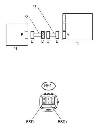
CHECK OCCUPANT CLASSIFICATION SYSTEM CIRCUIT (FOR OPEN) |
|
(a) Disconnect the connectors from the airbag sensor assembly and the occupant detection ECU. |
|
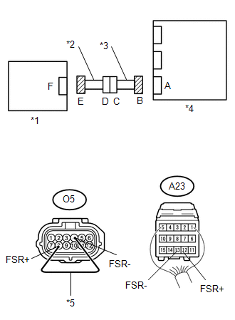
(b) Separate Seat :
Using a service wire, connect O5-8 (FSR+) and O5-4 (FSR-) of connector E.
NOTICE:
Do not forcibly insert a service wire into the terminals of the connector when connecting.
(c) Measure the resistance according to the value(s) in the table below.
Standard Resistance:
|
Tester Connection |
Condition |
Specified Condition |
|---|---|---|
|
A23-12 (FSR+) - A23-13 (FSR-) |
Always |
Below 1 Ω |
|
*1 |
Occupant Detection ECU |
|
*2 |
No. 1 Seat Wire |
|
*3 |
Floor Wire |
|
*4 |
Airbag Sensor Assembly |
|
*5 |
Service Wire |
| NG | |
GO TO STEP 13 |
|
|
6. |
CHECK OCCUPANT CLASSIFICATION SYSTEM CIRCUIT (FOR SHORT) |
|
(a) Disconnect the service wire from connector E. |
|
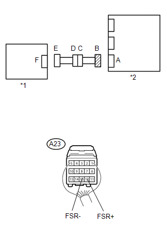
(b) Measure the resistance according to the value(s) in the table below.
Standard Resistance:
|
Tester Connection |
Condition |
Specified Condition |
|---|---|---|
|
A23-12 (FSR+) - A23-13 (FSR-) |
Always |
1 MΩ or Higher |
|
*1 |
Occupant Detection ECU |
|
*2 |
Airbag Sensor Assembly |
| NG | |
GO TO STEP 14 |
|
|
7. |
CHECK OCCUPANT CLASSIFICATION SYSTEM CIRCUIT (TO B+) |
|
(a) Connect the negative (-) terminal cable to the battery, and wait for at least 2 seconds. |
|
(b) Turn the ignition switch to ON.
(c) Measure the voltage according to the value(s) in the table below.
Standard Voltage:
|
Tester Connection |
Switch Condition |
Specified Condition |
|---|---|---|
|
A23-12 (FSR+) - Body ground |
Ignition switch ON |
Below 1 V |
|
A23-13 (FSR-) - Body ground |
Ignition switch ON |
Below 1 V |
|
*1 |
Occupant Detection ECU |
|
*2 |
Airbag Sensor Assembly |
| NG | |
GO TO STEP 15 |
|
|
8. |
CHECK OCCUPANT CLASSIFICATION SYSTEM CIRCUIT (TO GROUND) |
|
(a) Turn the ignition switch off. |
|
(b) Disconnect the negative (-) terminal cable from the battery, and wait for at least 90 seconds.
(c) Measure the resistance according to the value(s) in the table below.
Standard Resistance:
|
Tester Connection |
Condition |
Specified Condition |
|---|---|---|
|
A23-12 (FSR+) - Body ground |
Always |
1 MΩ or Higher |
|
A23-13 (FSR-) - Body ground |
Always |
1 MΩ or Higher |
|
*1 |
Occupant Detection ECU |
|
*2 |
Airbag Sensor Assembly |
| NG | |
GO TO STEP 16 |
|
|
9. |
CHECK AIRBAG SENSOR ASSEMBLY |
(a) Turn the ignition switch off.
(b) Disconnect the negative (-) terminal cable from the battery, and wait for at least 90 seconds.
(c) Replace the airbag sensor assembly (See page
).
HINT:
Perform the inspection using parts from a normal vehicle when possible.
(d) Connect the connectors to the airbag sensor assembly.
(e) Connect the negative (-) terminal cable to the battery, and wait for at least 2 seconds.
(f) Turn the ignition switch to ON, and wait for at least 60 seconds.
(g) Clear any DTCs stored in the memory (See page
).
(h) Turn the ignition switch off.
(i) Turn the ignition switch to ON, and wait for at least 60 seconds.
(j) Check for DTCs (See page ).
|
Result |
Proceed to |
|---|---|
|
DTC B1650/32 is output |
A |
|
DTC B1650/32 is not output |
B |
HINT:
DTCs other than B1650/32 may be output at this time, but they are not related to this check.
| B | |
END |
|
|
10. |
REPLACE OCCUPANT DETECTION ECU |
(a) Turn the ignition switch off.
(b) Disconnect the negative (-) terminal cable from the battery, and wait for at least 90 seconds.
(c) Replace the occupant detection ECU (See page
).
|
|
11. |
PERFORM ZERO POINT CALIBRATION |
(a) Connect the negative (-) terminal cable to the battery.
(b) Connect the Techstream to the DLC3.
(c) Turn the ignition switch to ON.
(d) Using the Techstream, perform the zero point calibration (See page
).
OK:
COMPLETED is displayed on the tester.
|
|
12. |
PERFORM SENSITIVITY CHECK |
(a) Using the Techstream, perform the sensitivity check (See page
).
Standard Value:
27 to 33 kg (59.52 to 72.75 lb)
| NEXT | |
END |
|
13. |
CHECK NO. 1 SEAT WIRE (FOR OPEN) |
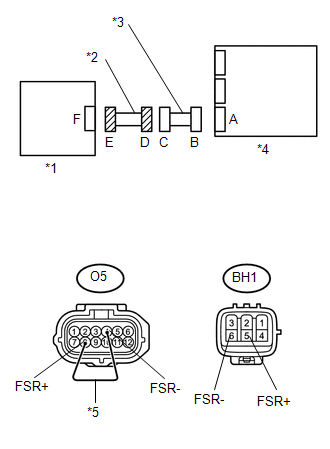
|
(a) Disconnect the No. 1 seat wire connector from the instrument panel wire. |
|
HINT:
The service wire has already been inserted into connector E.
(b) Measure the resistance according to the value(s) in the table below.
Standard Resistance:
|
Tester Connection |
Condition |
Specified Condition |
|---|---|---|
|
BH1-5 (FSR+) - BH1-6 (FSR-) |
Always |
Below 1 Ω |
|
*1 |
Occupant Detection ECU |
|
*2 |
No. 1 Seat Wire |
|
*3 |
Floor Wire |
|
*4 |
Airbag Sensor Assembly |
|
*5 |
Service Wire |
| OK | |
REPLACE FLOOR WIRE |
| NG | |
REPLACE NO. 1 SEAT WIRE |
|
14. |
CHECK NO. 1 SEAT WIRE (FOR SHORT) |
|
(a) Disconnect the No. 1 seat wire connector from the instrument panel wire. |
|
(b) Measure the resistance according to the value(s) in the table below.
Standard Resistance:
|
Tester Connection |
Condition |
Specified Condition |
|---|---|---|
|
BH1-5 (FSR+) - BH1-6 (FSR-) |
Always |
1 MΩ or Higher |
|
*1 |
Occupant Detection ECU |
|
*2 |
No. 1 Seat Wire |
|
*3 |
Floor Wire |
|
*4 |
Airbag Sensor Assembly |
| OK | |
REPLACE FLOOR WIRE |
| NG | |
REPLACE NO. 1 SEAT WIRE |
|
15. |
CHECK NO. 1 SEAT WIRE (TO B+) |
|
(a) Disconnect the No. 1 seat wire connector from the instrument panel wire. |
|
(b) Connect the negative (-) terminal cable to the battery, and wait for at least 2 seconds.
(c) Turn the ignition switch to ON.
(d) Measure the voltage according to the value(s) in the table below.
Standard Voltage:
|
Tester Connection |
Switch Condition |
Specified Condition |
|---|---|---|
|
BH1-5 (FSR+) - Body ground |
Ignition switch ON |
Below 1 V |
|
BH1-6 (FSR-) - Body ground |
Ignition switch ON |
Below 1 V |
|
*1 |
Occupant Detection ECU |
|
*2 |
No. 1 Seat Wire |
|
*3 |
Floor Wire |
|
*4 |
Airbag Sensor Assembly |
| OK | |
REPLACE FLOOR WIRE |
| NG | |
REPLACE NO. 1 SEAT WIRE |
|
16. |
CHECK NO. 1 SEAT WIRE (TO GROUND) |
|
(a) Disconnect the No. 1 seat wire connector from the instrument panel wire. |
|
(b) Measure the resistance according to the value(s) in the table below.
Standard Resistance:
|
Tester Connection |
Condition |
Specified Condition |
|---|---|---|
|
BH1-5 (FSR+) - Body ground |
Always |
1 MΩ or Higher |
|
BH1-6 (FSR-) - Body ground |
Always |
1 MΩ or Higher |
|
*1 |
Occupant Detection ECU |
|
*2 |
No. 1 Seat Wire |
|
*3 |
Floor Wire |
|
*4 |
Airbag Sensor Assembly |
| OK | |
REPLACE FLOOR WIRE |
| NG | |
REPLACE NO. 1 SEAT WIRE |
 Seat Belt Buckle Switch LH Circuit Malfunction (B1656/38)
DESCRIPTION
The seat belt buckle switch LH circuit consists of the airbag sensor assembly
and the front seat inner belt assembly LH (seat belt buckle switch LH).
DTC B1655/37 is stored when a malf ...
 Seat Position Airbag Sensor Circuit Malfunction (B1653/35)
DESCRIPTION
The seat position airbag sensor circuit consists of the airbag sensor assembly
and the seat position airbag sensor.
DTC B1653/35 is stored when a malfunction is detected in the seat po ...
Other materials:
Radar Cruise Control Presence Determination Malfunction (Engine / HV) (C1A52)
DESCRIPTION
DTC C1A52 is stored when the ECM cannot recognize the millimeter wave radar sensor
assembly.
DTC No.
Detection Item
DTC Detection Condition
Trouble Area
C1A52
Radar Cruise Control Presence Determination Malfuncti ...
Front Passenger Side Seat Belt Warning Light Malfunction
DESCRIPTION
The occupant classification ECU detects the state of the front seat inner belt
assembly RH and load sensor when the front passenger side seat is occupied with
the ignition switch ON. If the front passenger side seat belt is not fastened, the
front passenger side seat belt warning ...
Diagnostic Trouble Code Chart
DIAGNOSTIC TROUBLE CODE CHART
HINT:
If a trouble code is output during the DTC check, inspect the trouble areas listed
for that code. For details of the code, refer to "See page" in the DTC chart.
Wireless Door Lock Control System
DTC Code
Detection Item
...
