Toyota Tacoma (2015-2018) Service Manual: Removal
REMOVAL
PROCEDURE
1. REMOVE INTAKE AIR SURGE TANK ASSEMBLY
(See page .gif) )
)
2. DISCONNECT NO. 2 FUEL TUBE SUB-ASSEMBLY
|
(a) Disengage the 2 clamps. |
|
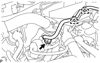
(b) Disconnect the No. 2 fuel tube sub-assembly from the fuel tube sub-assembly
(See page ).
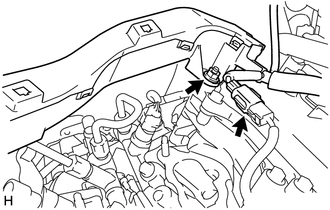
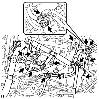
3. DISCONNECT ENGINE WIRE
|
(a) for LH Side: (1) Remove the nut and disconnect the engine wire from the cylinder head cover sub-assembly LH. (2) Disconnect the connector. |
|
|
(b) for RH Side: (1) Disengage the 2 clamps. (2) Disconnect the 13 connectors. (3) Remove the 2 bolts and disconnect the engine wire. |
|
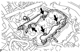
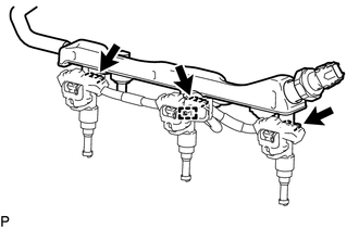
4. REMOVE FUEL DELIVERY PIPE SUB-ASSEMBLY
NOTICE:
- Do not remove the fuel pressure sensor from the fuel delivery pipe sub-assembly.
- If a fuel pressure sensor is removed, replace the fuel delivery pipe sub-assembly (fuel pressure sensor) with a new one.
|
(a) Disconnect the connector. |
|
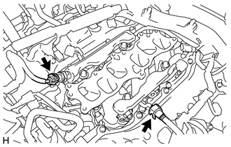
(b) Disconnect the No. 1 fuel tube sub-assembly from the fuel delivery pipe sub-assembly
(See page ).
|
(c) Remove the 4 bolts and fuel delivery pipe sub-assembly. NOTICE: When removing the fuel delivery pipe sub-assembly, hold the pipe by both ends and pull it straight upward. |
|
(d) Remove the 4 No. 1 delivery pipe spacers from the intake manifold.
(e) Remove the 6 injector vibration insulators from the intake manifold.
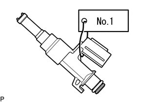
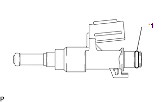
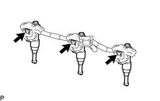
5. REMOVE FUEL INJECTOR ASSEMBLY
NOTICE:
For reinstallation, attach a tag or label to the injector shaft.
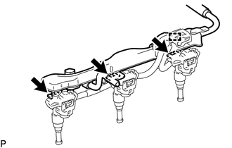
(a) for LH Side:
(1) Disengage the clamp.
(2) Remove the 3 fuel injector assemblies with No. 5 engine wire from the fuel delivery pipe sub-assembly.
|
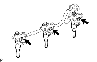
(3) Disconnect the 3 connectors and remove the 3 fuel injector assemblies. |
|
|
(4) Remove the O-ring from the fuel injector assembly. Text in Illustration
|
|
(b) for RH Side:
(1) Disengage the clamp.
(2) Remove the 3 fuel injector assemblies with No. 5 engine wire from the fuel delivery pipe sub-assembly.
|
(3) Disconnect the 3 connectors and remove the 3 fuel injector assemblies. |
|
|
(4) Remove the O-ring from the fuel injector assembly. Text in Illustration
|
|
 Inspection
INSPECTION
PROCEDURE
1. INSPECT FUEL INJECTOR ASSEMBLY
(a) Measure the resistance according to the value(s) in the table below.
Standard Resistance:
Tester Connection
Condi ...
 Installation
INSTALLATION
CAUTION / NOTICE / HINT
HINT:
Perform "Inspection After Repairs" after replacing the fuel injector assembly
(See page ).
PROCEDURE
1. INSTALL FUEL INJECTOR ASSEMBLY
HIN ...
Other materials:
Pressure Control Solenoid "A" Performance (Shift Solenoid Valve SL1) (P0746)
SYSTEM DESCRIPTION
The ECM uses the vehicle speed signal and signals from the transmission revolution
sensors (NT, SP2) to detect the actual gear (1st, 2nd, 3rd, 4th, 5th or 6th gear).
The ECM compares the actual gear with the shift schedule in the ECM memory to
detect mechanical problems of t ...
Data Signal Circuit between Navigation Receiver Assembly and Extension Module
DESCRIPTION
The stereo component tuner assembly sends the sound data signal or image data
signal from a device to the navigation receiver assembly via this circuit.
WIRING DIAGRAM
CAUTION / NOTICE / HINT
NOTICE:
After replacing the stereo component tuner assembly of vehicles subscribed to
...
Before Starting Adjustment
BEFORE STARTING ADJUSTMENT
CAUTION / NOTICE / HINT
NOTICE:
When replacing the windshield glass of a vehicle equipped with a forward recognition
camera, make sure to use a Toyota genuine part. If a non-Toyota genuine part is
used, the forward recognition camera may not be able to be installed ...
