Toyota Tacoma (2015-2018) Service Manual: Installation
INSTALLATION
CAUTION / NOTICE / HINT
HINT:
Perform "Inspection After Repairs" after replacing the fuel injector assembly
(See page .gif) ).
).
PROCEDURE
1. INSTALL FUEL INJECTOR ASSEMBLY
HINT:
Perform "Inspection After Repairs" after replacing the fuel injector assembly
(See page ).
(a) Apply gasoline to new O-rings and install them to each injector.
NOTICE:
Check that there is no damage or foreign material in the groove of the injector when installing the O-rings.
|
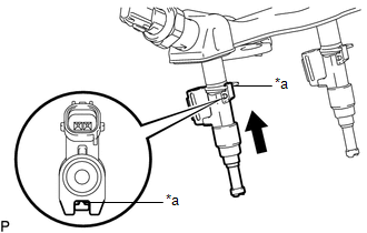
(b) Install the fuel injector assemblies to the fuel delivery pipe sub-assembly. Text in Illustration
NOTICE:
|
|
2. INSTALL FUEL DELIVERY PIPE SUB-ASSEMBLY
NOTICE:
- Do not remove the fuel pressure sensor from the fuel delivery pipe sub-assembly.
- If a fuel pressure sensor is removed, replace the fuel delivery pipe sub-assembly (fuel pressure sensor) with a new one.
(a) Install 6 new injection vibration insulators to the intake manifold.
(b) Install the 4 No. 1 delivery pipe spacers to the intake manifold.
(c) Install the fuel delivery pipe sub-assembly (with fuel injector assembly) to the intake manifold.
NOTICE:
Be careful not to twist the O-ring.
|
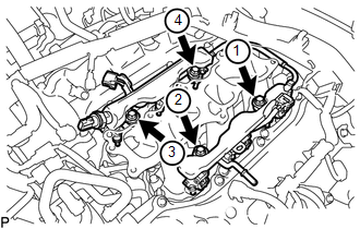
(d) Install the fuel injector assemblies to the fuel delivery pipe sub-assemblies with the 4 bolts in the order shown in the illustration. Torque: 17 N·m {173 kgf·cm, 13 ft·lbf} |
|
(e) Connect the No. 1 fuel tube sub-assembly to the fuel delivery pipe sub-assembly
(See page ).
(f) Connect the connector.
3. CONNECT ENGINE WIRE
(a) for RH Side:
(1) Connect the engine wire with the 2 bolts.
Torque:
8.0 N·m {82 kgf·cm, 71 in·lbf}
(2) Connect the 13 connectors.
(3) Engage the 2 clamps.
(b) for LH Side:
(1) Connect the connector.
(2) Connect the engine wire to the cylinder head cover sub-assembly LH with the nut.
Torque:
8.0 N·m {82 kgf·cm, 71 in·lbf}
4. CONNECT NO. 2 FUEL TUBE SUB-ASSEMBLY
(a) Connect the No. 2 fuel tube sub-assembly to the fuel tube sub-assembly (See
page ).
(b) Engage the 2 clamps.
5. INSTALL INTAKE AIR SURGE TANK ASSEMBLY
(See page )
 Removal
REMOVAL
PROCEDURE
1. REMOVE INTAKE AIR SURGE TANK ASSEMBLY
(See page )
2. DISCONNECT NO. 2 FUEL TUBE SUB-ASSEMBLY
(a) Disengage the 2 clamps.
...
 Fuel Main Valve
Components
COMPONENTS
ILLUSTRATION
Removal
REMOVAL
PROCEDURE
1. REMOVE FUEL SUCTION TUBE WITH PUMP AND GAUGE ASSEMBLY
(See page )
2. REMOVE FUEL SENDER GAUGE ASSEMBLY
3. REMOVE NO. ...
Other materials:
Installation
INSTALLATION
PROCEDURE
1. INSTALL FUEL SUCTION TUBE SET GASKET
(a) Ensure gasket groove is clean and free of foreign particles.
(b) Install a new gasket onto the fuel tank.
(c) Make sure that the gasket sits in the groove.
2. INSTALL FUEL SU ...
Installation
INSTALLATION
PROCEDURE
1. INSTALL LOWER NO. 1 INSTRUMENT PANEL AIRBAG ASSEMBLY
(a) Connect the airbag connector.
NOTICE:
When handling the airbag connector, take care not to damage the airbag
wire harness.
(b) Push in the airbag conn ...
On-vehicle Inspection
ON-VEHICLE INSPECTION
PROCEDURE
1. INSPECT STEERING PAD (for Vehicle not Involved in Collision)
(a) Perform a diagnostic system check (See page
).
(b) With the steering pad installed on the vehicle, perform a visual check. If
there are any defects as mentioned below, replace the steering pad ...
