Toyota Tacoma (2015-2018) Service Manual: Components
COMPONENTS
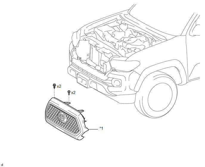
ILLUSTRATION
|
*1 |
RADIATOR GRILLE |
- |
- |
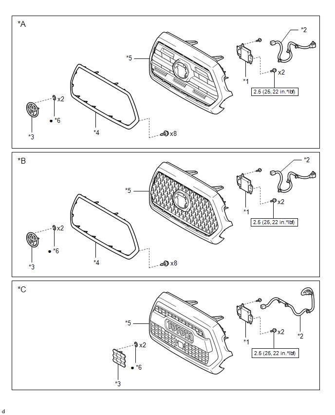
ILLUSTRATION
|
*A |
for Type A |
*B |
for Type B |
|
*C |
for Type C |
- |
- |
|
*1 |
MILLIMETER WAVE RADAR SENSOR ASSEMBLY |
*2 |
MILLIMETER WAVE RADAR WIRE |
|
*3 |
NO. 1 RADIATOR GRILLE GARNISH |
*4 |
RADIATOR GRILLE MOULDING |
|
*5 |
RADIATOR GRILLE SUB-ASSEMBLY |
*6 |
SPRING NUT |
.png) |
N*m (kgf*cm, ft.*lbf): Specified torque |
â—Ź |
Non-reusable part |
 Radiator Grille
...
 Removal
REMOVAL
PROCEDURE
1. REMOVE RADIATOR GRILLE
(a) w/ Toyota Safety Sense P
(1) Disconnect the connector.
(2) Disengage the clamp.
(b ...
Other materials:
Key-off Operation Function Operates even if Operating Conditions are not Satisfied
DESCRIPTION
When the front doors are closed, each power window regulator motor assembly
can control its power window operation for approximately 43 seconds after
the ignition switch is turned from ON to off by receiving operation permission
signals from the main body ECU.
How ...
Removal
REMOVAL
PROCEDURE
1. PRECAUTION
CAUTION:
Be sure to read Precaution thoroughly before servicing (See page
).
NOTICE:
After turning the ignition switch off, waiting time may be required before disconnecting
the cable from the negative (-) battery terminal. Therefore, make sure to read the
...
Manual Shifting Test
MANUAL SHIFTING TEST
1. PERFORM MANUAL SHIFTING TEST
HINT:
Using this test, it can be determined whether a problem is in an electrical
circuit or if it is a mechanical problem in the transmission.
If any abnormalities are found in the following test, the problem is
in the tran ...
