Toyota Tacoma (2015-2018) Service Manual: Removal
REMOVAL
PROCEDURE
1. PRECAUTION
NOTICE:
After turning the ignition switch off, waiting time may be required before disconnecting the cable from the negative (-) battery terminal. Therefore, make sure to read the disconnecting the cable from the negative (-) battery terminal notices before proceeding with work.
Click here .gif)
2. DISCONNECT CABLE FROM NEGATIVE BATTERY TERMINAL
NOTICE:
When disconnecting the cable, some systems need to be initialized after the cable is reconnected.
Click here
3. REMOVE HEATED OXYGEN SENSOR
Click here
4. REMOVE TAIL EXHAUST PIPE ASSEMBLY
|
(a) Remove the 2 bolts to separate the tail exhaust pipe assembly. |
|
(b) Disconnect the 4 exhaust pipe supports to remove the tail exhaust pipe assembly.
5. REMOVE CENTER EXHAUST PIPE ASSEMBLY
|
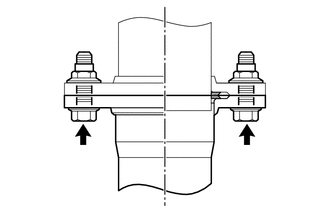
(a) Remove the 2 bolts and 2 compression springs. |
|
.png)
|
(b) Remove the 2 bolts to separate the center exhaust pipe assembly. |
|
.png)
(c) Disconnect the exhaust pipe support to remove the center exhaust pipe assembly.
6. REMOVE CENTER NO. 2 FLOOR HEAT INSULATOR SUB-ASSEMBLY (for 4WD)
|
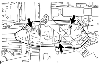
(a) Remove the 3 nuts and center No. 2 floor heat insulator sub-assembly. |
|
7. REMOVE EXHAUST PIPE STOPPER BRACKET (for 4WD)
|
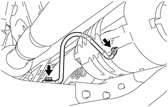
(a) Remove the 2 bolts and exhaust pipe stopper bracket. |
|
8. REMOVE FRONT NO. 2 EXHAUST PIPE ASSEMBLY
|
(a) Remove the 2 nuts to separate the front No. 2 exhaust pipe assembly from the exhaust manifold LH. |
|
.png)
(b) Disconnect the exhaust pipe support to remove the front No. 2 exhaust pipe assembly.
9. REMOVE FRONT EXHAUST PIPE ASSEMBLY
|
(a) Remove the 2 nuts and front exhaust pipe assembly. |
|
.png)
10. REMOVE MONOLITHIC CONVERTER PROTECTOR
|
(a) Remove the bolt and clamp. |
|
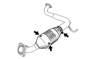
(b) Remove the 2 bolts, 2 nuts and upper monolithic converter protector and lower monolithic converter protector.
 Components
COMPONENTS
ILLUSTRATION
ILLUSTRATION
...
 Installation
INSTALLATION
PROCEDURE
1. REMOVE MONOLITHIC CONVERTER PROTECTOR
(a) Install the upper monolithic converter protector and lower monolithic converter
protector with the 2 bolts and 2 nuts.
Torque: ...
Other materials:
Initialization
INITIALIZATION
1. INITIALIZE SLIDING ROOF SYSTEM
NOTICE:
Before starting this operation, make sure that the guide rails are not
deformed and there is no foreign matter on the guide rails.
When the sliding roof glass sub-assembly or sliding roof drive cable
sub-assembly is adju ...
Precaution
PRECAUTION
1. PRECAUTION
(a) Before starting work on the fuel system, including inspections and repairs,
disconnect the cable from the negative (-) battery terminal.
(b) Do not smoke or work near fire when performing work on the fuel system.
(c) Keep gasoline away from rubber or leather parts. ...
System Diagram
SYSTEM DIAGRAM
Communication Table
Sender
Receiver
Signal
Line
ECM
Combination Meter Assembly
Cruise main indicator light signal
CAN
Skid Control ECU
ECM
Vehicle st ...
