Toyota Tacoma (2015-2018) Service Manual: Removal
REMOVAL
PROCEDURE
1. REMOVE TIMING CHAIN COVER ASSEMBLY
(See page .gif) )
)
2. SEPARATE NO. 2 WATER BY-PASS PIPE (for Vacuum Brake Booster)
3. REMOVE VACUUM PUMP ASSEMBLY (for Vacuum Brake Booster)
4. SET NO. 1 CYLINDER TO TDC/COMPRESSION
5. REMOVE NO. 1 CHAIN TENSIONER ASSEMBLY
6. REMOVE CHAIN TENSIONER SLIPPER
7. REMOVE CHAIN SUB-ASSEMBLY
8. REMOVE CAMSHAFT TIMING GEARS AND NO. 2 CHAIN (for Bank 1)
|
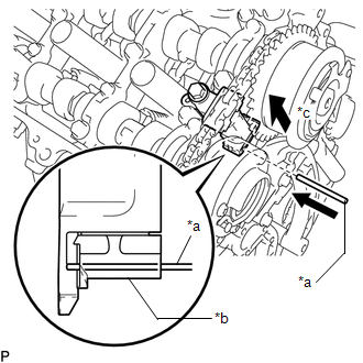
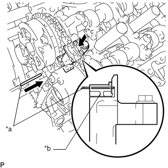
(a) While raising the No. 2 chain tensioner assembly, insert a pin of 1.0 mm (0.0394 in.) diameter into the hole to hold the No. 2 chain tensioner assembly. Text in Illustration
|
|
|
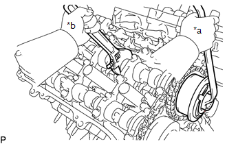
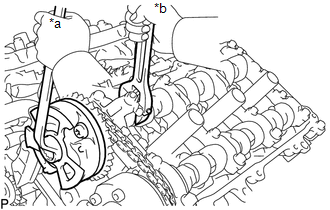
(b) Using a wrench to hold the hexagonal portion of each camshaft, loosen the camshaft timing gear bolts of the camshaft timing gear assembly and the camshaft timing exhaust gear assembly RH. Text in Illustration
NOTICE:
|
|
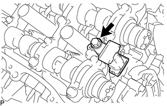
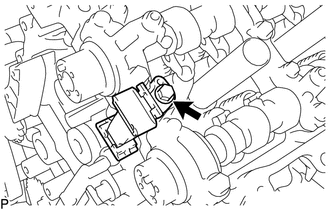
(c) Remove the 2 bolts and the camshaft timing gear assembly together with the No. 2 chain.
9. REMOVE NO. 2 CHAIN TENSIONER ASSEMBLY
|
(a) Remove the bolt and No. 2 chain tensioner assembly. |
|
10. REMOVE CAMSHAFT BEARING CAP (for Bank 1)
|
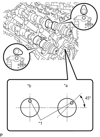
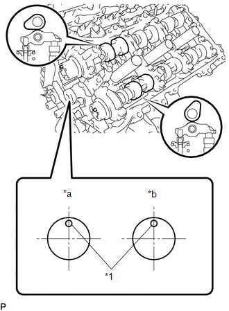
(a) Check that the camshafts are positioned as shown in the illustration. Text in Illustration
|
|
|
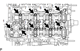
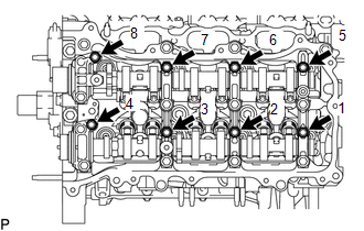
(b) Uniformly loosen and remove the 9 bearing cap bolts in several steps and in the sequence shown in the illustration. |
|
|
(c) Uniformly loosen and remove the 15 bearing cap bolts in several steps and in the sequence shown in the illustration. NOTICE: Uniformly loosen the bolts while keeping the camshaft level. |
|
11. REMOVE FUEL PUMP LIFTER HOUSING
|
(a) Remove the fuel pump lifter housing. |
|
12. REMOVE CAMSHAFT
13. REMOVE NO. 2 CAMSHAFT
14. REMOVE CAMSHAFT HOUSING SUB-ASSEMBLY RH
|
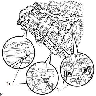
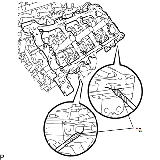
(a) Remove the camshaft housing RH by prying between the cylinder head and camshaft housing RH with a screwdriver. Text in Illustration
NOTICE: Be careful not to damage the contact surfaces of the cylinder head and camshaft housing RH. HINT: Tape the screwdriver tip before use. |
|
15. REMOVE CAMSHAFT TIMING GEARS AND NO. 2 CHAIN (for Bank 2)
|
(a) While pushing down the No. 3 chain tensioner assembly, insert a pin of 1.0 mm (0.0394 in.) diameter into the hole to hold the No. 3 chain tensioner assembly. Text in Illustration
|
|
|
(b) Using a wrench to hold the hexagonal portion of each camshaft, loosen the camshaft timing gear bolts of the camshaft timing gear assembly and the camshaft timing exhaust gear assembly LH. Text in Illustration
NOTICE:
|
|
(c) Remove the 2 bolts and the camshaft timing gear together with the No. 2 chain.
16. REMOVE NO. 3 CHAIN TENSIONER ASSEMBLY
|
(a) Remove the bolt and No. 3 chain tensioner assembly. |
|
17. REMOVE CAMSHAFT BEARING CAP (for Bank 2)
|
(a) Check that the camshafts are positioned as shown in the illustration. Text in Illustration
|
|
|
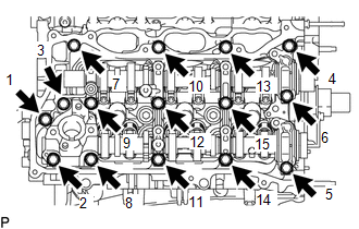
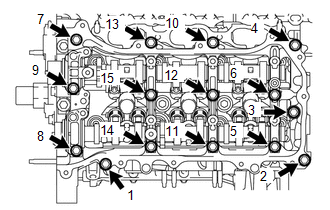
(b) Uniformly loosen and remove the 8 bearing cap bolts in several steps and in the sequence shown in the illustration. |
|
|
(c) Uniformly loosen and remove the 13 bearing cap bolts in several steps and in the sequence shown in the illustration. NOTICE: Uniformly loosen the bolts while keeping the camshaft level. |
|
(d) Remove the 5 camshaft bearing caps.
18. REMOVE NO. 3 CAMSHAFT SUB-ASSEMBLY
19. REMOVE NO. 4 CAMSHAFT SUB-ASSEMBLY
20. REMOVE CAMSHAFT HOUSING SUB-ASSEMBLY LH
|
(a) Remove the camshaft housing LH by prying between the cylinder head LH and camshaft housing LH with a screwdriver. Text in Illustration
NOTICE: Be careful not to damage the contact surfaces of the cylinder head and camshaft housing LH. HINT: Tape the screwdriver tip before use. |
|
21. REMOVE NO. 1 CHAIN VIBRATION DAMPER
22. REMOVE NO. 2 CHAIN VIBRATION DAMPER
23. REMOVE NO. 1 VALVE ROCKER ARM SUB-ASSEMBLY
(a) Remove the 24 No. 1 valve rocker arms.
HINT:
Arrange the removed parts in the correct order.
24. REMOVE VALVE LASH ADJUSTER ASSEMBLY
(a) Remove the 24 valve lash adjusters from the cylinder head.
HINT:
Arrange the removed parts in the correct order.
25. REMOVE VALVE STEM CAP
(a) Remove the 24 valve stem caps.
HINT:
Arrange the removed parts in the correct order.
26. REMOVE REAR WATER BY-PASS JOINT
27. REMOVE NO. 2 FUEL PIPE SUB-ASSEMBLY
28. REMOVE FUEL DELIVERY PIPE ASSEMBLY LH (FUEL PRESSURE SENSOR)
29. REMOVE FUEL DELIVERY PIPE RH
30. REMOVE FUEL INJECTOR ASSEMBLY
31. REMOVE FUEL INJECTOR SEAL
32. REMOVE CYLINDER HEAD SUB-ASSEMBLY
|
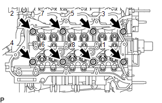
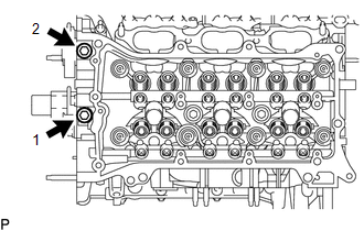
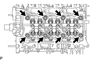
(a) Using a 10 mm bi-hexagon wrench, uniformly loosen the 8 bolts in the sequence shown in the illustration. Remove the 8 cylinder head bolts and plate washers. NOTICE:
HINT: Be sure to keep separate the removed parts for each installation position. |
|
(b) Remove the cylinder head.
33. REMOVE CYLINDER HEAD GASKET
34. REMOVE CYLINDER HEAD LH
|
(a) Uniformly loosen and remove the 2 bolts in the sequence shown in the illustration. |
|
|
(b) Using a 10 mm bi-hexagon wrench, uniformly loosen the 8 bolts in the sequence shown in the illustration. Remove the 8 cylinder head bolts and plate washers. NOTICE:
HINT: Be sure to keep separate the removed parts for each installation position. |
|
(c) Remove the cylinder head LH.
35. REMOVE NO. 2 CYLINDER HEAD GASKET
36. INSPECT CYLINDER HEAD SET BOLT
 Components
COMPONENTS
ILLUSTRATION
ILLUSTRATION
ILLUSTRATION
*1
CAMSHAFT
*2
CAMSHAFT BEARING CAP
*3
CAMSHAFT HOUSING SUB-ASSEMBLY ...
 Drive Belt
Components
COMPONENTS
ILLUSTRATION
Precaution
PRECAUTION
NOTICE:
Do not apply or add oil or grease to the belt tensioner to prevent abnormal
noises from the belt tensioner pull ...
Other materials:
Disassembly
DISASSEMBLY
PROCEDURE
1. REMOVE GENERATOR PULLEY
(a) Mount the generator assembly in the vise between aluminum plates.
NOTICE:
Do not overtighten the vise.
(b) Install SST 1-A to the generator pulley shaft.
Text in Illustration
*a
Hold
Turn
...
Stop Light Control Relay Malfunction (C1380)
DESCRIPTION
The skid control ECU (brake actuator assembly) inputs the stop light switch signal
and detect the status of the brake operation.
DTC No.
Detection Item
DTC Detection Condition
Trouble Area
C1380
Stop Light Contro ...
Sleep Operation Failure of Occupant Classification ECU (B1796)
DESCRIPTION
During sleep mode, the occupant detection ECU monitors the condition of each
sensor while the ignition switch is off. In this mode, if the occupant detection
ECU detects an internal malfunction, DTC B1796 is set.
DTC No.
DTC Detections Conditions
Tr ...
