Toyota Tacoma (2015-2018) Service Manual: Sound Signal Circuit between Radio Receiver and Stereo Jack Adapter
DESCRIPTION
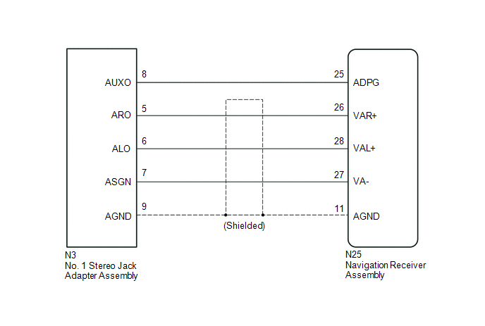
The No. 1 stereo jack adapter assembly sends the sound signal from an external device to the navigation receiver assembly via this circuit.
If there is an open or short in the circuit, sound cannot be heard from the speakers even if there is no malfunction in the stereo component amplifier assembly, navigation receiver assembly or speakers.
WIRING DIAGRAM
PROCEDURE
|
1. |
CHECK HARNESS AND CONNECTOR (NAVIGATION RECEIVER ASSEMBLY - NO. 1 STEREO JACK ADAPTER ASSEMBLY) |
(a) Disconnect the N25 navigation receiver assembly connector.
(b) Disconnect the N3 No. 1 stereo jack adapter assembly connector.
(c) Measure the resistance according to the value(s) in the table below.
Standard Resistance:
|
Tester Connection |
Condition |
Specified Condition |
|---|---|---|
|
N25-25 (ADPG) - N3-8 (AUXO) |
Always |
Below 1 Ω |
|
N25-26 (VAR+) - N3-5 (ARO) |
Always |
Below 1 Ω |
|
N25-28 (VAL+) - N3-6 (ALO) |
Always |
Below 1 Ω |
|
N25-27 (VA-) - N3-7 (ASGN) |
Always |
Below 1 Ω |
|
N25-11 (AGND) - N3-9 (AGND) |
Always |
Below 1 Ω |
|
N25-25 (ADPG) - Body ground |
Always |
10 kΩ or higher |
|
N25-26 (VAR+) - Body ground |
Always |
10 kΩ or higher |
|
N25-28 (VAL+) - Body ground |
Always |
10 kΩ or higher |
|
N25-27 (VA-) - Body ground |
Always |
10 kΩ or higher |
|
N25-11 (AGND) - Body ground |
Always |
10 kΩ or higher |
| OK | .gif) |
PROCEED TO NEXT SUSPECTED AREA SHOWN IN PROBLEM SYMPTOMS TABLE |
| NG | |
REPAIR OR REPLACE HARNESS OR CONNECTOR |
 Data Signal Circuit between Stereo Jack Adapter and Extension Module
DESCRIPTION
The No. 1 stereo jack adapter assembly sends the sound data signal or image data
signal from a USB device to the navigation receiver assembly via this circuit.
WIRING DIAGRAM
PROCED ...
 Data Signal Circuit between Navigation Receiver Assembly and Extension Module
DESCRIPTION
The stereo component tuner assembly sends the sound data signal or image data
signal from a device to the navigation receiver assembly via this circuit.
WIRING DIAGRAM
CAUTION / NOT ...
Other materials:
Fender Panel Mudguard
Components
COMPONENTS
ILLUSTRATION
ILLUSTRATION
Installation
INSTALLATION
CAUTION / NOTICE / HINT
HINT:
Use the same procedure for the RH side and LH side.
The following procedure is for the LH side.
PROCEDURE
1. INSTALL FRONT FENDER MUDGUARD
(a) Install the fron ...
Short in Torque Converter Clutch Solenoid Circuit (Shift Solenoid Valve SL)
(P2769,P2770)
DESCRIPTION
Shift solenoid valve SL is turned on and off by signals from the ECM to control
the hydraulic pressure acting on the lock-up relay valve, which then controls operation
of the lock-up clutch.
DTC No.
DTC Detection Condition
Trouble Area
...
Oil Pressure Switch
Components
COMPONENTS
ILLUSTRATION
Removal
REMOVAL
PROCEDURE
1. REMOVE ENGINE OIL PRESSURE SWITCH ASSEMBLY
(a) Disengage the clamp and disconnect the engine oil pressure switch
connector.
(b) Using a 24 mm deep socket ...
