Toyota Tacoma (2015-2018) Service Manual: Components
COMPONENTS
ILLUSTRATION
ILLUSTRATION
ILLUSTRATION
|
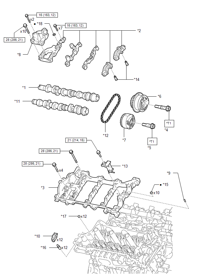
*1 |
CAMSHAFT |
*2 |
CAMSHAFT BEARING CAP |
|
*3 |
CAMSHAFT HOUSING SUB-ASSEMBLY RH |
*4 |
CAMSHAFT TIMING GEAR BOLT (for Intake Side of Bank 1) |
|
*5 |
CAMSHAFT TIMING GEAR BOLT (for Exhaust Side of Bank 1) |
*6 |
CAMSHAFT TIMING GEAR ASSEMBLY |
|
*7 |
CAMSHAFT TIMING EXHAUST GEAR ASSEMBLY RH |
*8 |
FUEL PUMP LIFTER HOUSING |
|
*9 |
NO. 1 STRAIGHT PIN |
*10 |
NO. 1 VALVE ROCKER ARM SUB-ASSEMBLY |
|
*11 |
NO. 2 CAMSHAFT |
*12 |
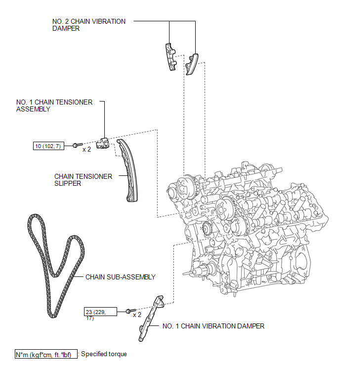
NO. 2 CHAIN SUB-ASSEMBLY |
|
*13 |
NO. 2 CHAIN TENSIONER ASSEMBLY |
*14 |
OIL CONTROL VALVE FILTER RH |
|
*15 |
RING PIN |
*16 |
VALVE LASH ADJUSTER ASSEMBLY |
|
*17 |
VALVE STEM CAP |
*18 |
GASKET |
.png) |
N*m (kgf*cm, ft.*lbf): Specified torque |
â—Ź |
Non-reusable part |
|
*T1 |
Type A: 120 N*m (1224 kgf*cm, 89 ft.*lbf) Type B: 95 N*m (969 kgf*cm, 70 ft.*lbf) |
- |
- |
ILLUSTRATION
|
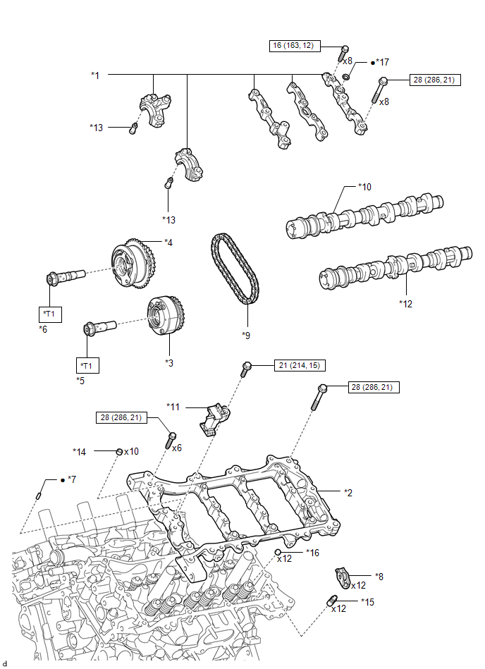
*1 |
CAMSHAFT BEARING CAP |
*2 |
CAMSHAFT HOUSING SUB-ASSEMBLY LH |
|
*3 |
CAMSHAFT TIMING EXHAUST GEAR ASSEMBLY LH |
*4 |
CAMSHAFT TIMING GEAR ASSEMBLY |
|
*5 |
CAMSHAFT TIMING GEAR BOLT (for Exhaust Side of Bank 2) |
*6 |
CAMSHAFT TIMING GEAR BOLT (for Intake Side of Bank 2) |
|
*7 |
NO. 1 STRAIGHT PIN |
*8 |
NO. 1 VALVE ROCKER ARM SUB-ASSEMBLY |
|
*9 |
NO. 2 CHAIN SUB-ASSEMBLY |
*10 |
NO. 3 CAMSHAFT SUB-ASSEMBLY |
|
*11 |
NO. 3 CHAIN TENSIONER ASSEMBLY |
*12 |
NO. 4 CAMSHAFT SUB-ASSEMBLY |
|
*13 |
OIL CONTROL VALVE FILTER LH |
*14 |
RING PIN |
|
*15 |
VALVE LASH ADJUSTER ASSEMBLY |
*16 |
VALVE STEM CAP |
|
*17 |
GASKET |
- |
- |
|
|
N*m (kgf*cm, ft.*lbf): Specified torque |
â—Ź |
Non-reusable part |
|
*T1 |
Type A: 120 N*m (1224 kgf*cm, 89 ft.*lbf) Type B: 95 N*m (969 kgf*cm, 70 ft.*lbf) |
- |
- |
ILLUSTRATION
ILLUSTRATION

 Removal
REMOVAL
PROCEDURE
1. REMOVE TIMING CHAIN COVER ASSEMBLY
(See page )
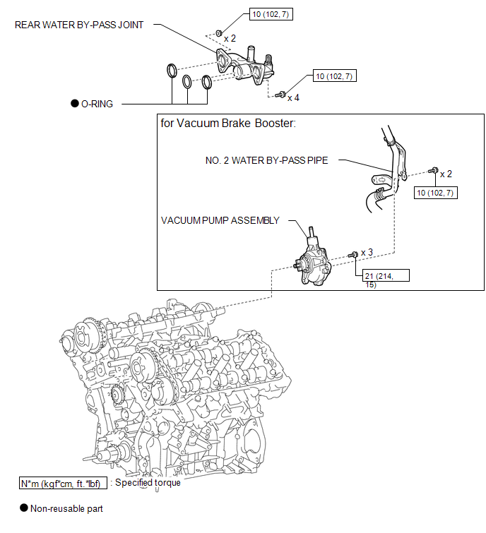
2. SEPARATE NO. 2 WATER BY-PASS PIPE (for Vacuum Brake Booster)
3. REMOVE VACUUM PUMP ASSEMBLY (for Vacuum Brake Booster)
...
Other materials:
How To Proceed With Troubleshooting
CAUTION / NOTICE / HINT
HINT:
Use the following procedure to troubleshoot the LIN communication system.
*: Use the Techstream.
PROCEDURE
1.
VEHICLE BROUGHT TO WORKSHOP
NEXT
...
Diagnosis System
DIAGNOSIS SYSTEM
1. DIAGNOSIS
(a) If the skid control ECU (master cylinder solenoid) detects a malfunction,
the ABS and/or BRAKE warning lights and the slip indicator lights come on in accordance
with the trouble area to warn the driver.
HINT:
The DTCs are simultaneously stored in th ...
System Diagram
SYSTEM DIAGRAM
Communication Table
Sender
Receiver
Signal
Communication Method
Airbag sensor assembly
Main body ECU
Front seat inner belt assembly LH buckle switch
CAN
Combination mete ...
