Toyota Tacoma (2015-2018) Service Manual: Removal
REMOVAL
CAUTION / NOTICE / HINT
NOTICE:
If one of the camshaft timing gear bolts is already removed, do not remove any other camshaft timing gear bolts.
PROCEDURE
1. REMOVE NO. 2 ENGINE UNDER COVER SUB-ASSEMBLY (w/ Off Road Package)
2. REMOVE NO. 1 ENGINE UNDER COVER SUB-ASSEMBLY
3. REMOVE CAMSHAFT TIMING OIL CONTROL SOLENOID ASSEMBLY
(See page .gif) )
)
4. SET NO. 1 CYLINDER TO TDC/COMPRESSION
|
(a) Turn the crankshaft clockwise to align the timing mark (cutout) on the crankshaft pulley assembly with the "0" timing mark on the timing chain cover assembly. Text in Illustration
|
|
.png)
|
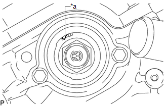
(b) Check that the protrusion on the inside of the camshaft timing gear assembly is at the top. Text in Illustration
HINT: If the protrusion is not at the top, rotate the crankshaft clockwise 360° and align the timing marks again. |
|
5. REMOVE CAMSHAFT TIMING GEAR BOLT
|
(a) Using SST, hold the crankshaft pulley assembly. SST: 09213-54015 91651-60855 SST: 09330-00021 |
|
.png)
|
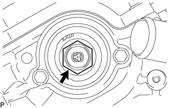
(b) Remove the camshaft timing gear bolt. NOTICE: Replace with a new part if it is dropped or if it receives a strong impact. |
|
 On-vehicle Inspection
ON-VEHICLE INSPECTION
PROCEDURE
1. INSPECT CAMSHAFT TIMING GEAR BOLT
(a) Remove the camshaft timing oil control solenoid assembly (See page
).
(b) Check that the plunger strokes when ...
 Installation
INSTALLATION
PROCEDURE
1. SET NO. 1 CYLINDER TO TDC/COMPRESSION
2. INSTALL CAMSHAFT TIMING GEAR BOLT
NOTICE:
There are different types of camshaft timing gear bolts. Make sure to check the
i ...
Other materials:
Air Outlet Damper Control Servo Motor Circuit (B1443/43)
DESCRIPTION
This No. 1 air conditioning radiator damper servo sub-assembly (for mode switching)
is controlled by the air conditioning amplifier assembly and moves the mode damper
to the desired position.
DTC No.
DTC Detection Condition
Trouble Area
...
ACC Signal Circuit
DESCRIPTION
This circuit detects whether the ignition switch is ACC or off, and sends this
information to the main body ECU (multiplex network body ECU).
WIRING DIAGRAM
CAUTION / NOTICE / HINT
NOTICE:
Inspect the fuses for circuits related to this system before performing
the fo ...
Transfer L4 Position Switch Circuit (C1268)
DESCRIPTION
DTC No.
Detection Item
DTC Detection Condition
Trouble Area
C1268
Transfer L4 Position Switch Circuit
Either of the following is detected:
The skid control ECU (brake actuator assembly) dete ...
