Toyota Tacoma (2015-2018) Service Manual: Short to GND in Immobiliser System Power Source Circuit (B278A)
DESCRIPTION
When there is a short to GND in the power supply for the transponder key amplifier of the engine switch, the certification ECU (smart key ECU assembly) stores this DTC.
|
DTC Code |
DTC Detection Condition |
Trouble Area |
DTC Output Confirmation Operation |
|---|---|---|---|
|
B278A |
A short to GND in the power supply of the transponder key amplifier of the engine switch (VC5 - VC5) (1 trip detection logic*). |
|
With the shift lever in P, the key held near the engine switch and an engine start operation is performed by pressing and holding the engine switch when the key battery is depleted. |
- *: Only output while a malfunction is present.
|
Vehicle Condition when Malfunction Detected |
Fail-safe Operation when Malfunction Detected |
|---|---|
|
Engine cannot be started when key battery is depleted by holding key near engine switch and pressing and holding engine switch with shift lever in P |
- |
|
DTC Code |
Data List and Active Test |
|---|---|
|
B278A |
- |
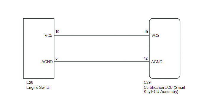
WIRING DIAGRAM
CAUTION / NOTICE / HINT
NOTICE:
- Before replacing the certification ECU (smart key ECU assembly), refer
to Registration (See page
.gif) ).
). - After performing repairs, perform the operation that fulfills the DTC output confirmation operation, and then confirm that no DTCs are output again.
PROCEDURE
|
1. |
CHECK CERTIFICATION ECU (SMART KEY ECU ASSEMBLY) |
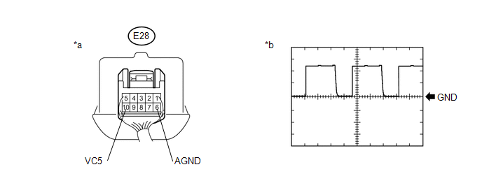
(a) Using an oscilloscope, check the waveform.
 Text in Illustration
|
*a |
Component with harness connected (Engine Switch) |
*b |
Waveform |
HINT:
Perform this inspection on the engine switch side.
Measurement Condition:
|
Tester Connection |
Condition |
Tool Setting |
Specified Condition |
|---|---|---|---|
|
E28-10 (VC5) - E28-6 (AGND) |
Engine switch off, key not in cabin, within 30 seconds after engine switch pressed |
2 V/DIV., 200 ms./DIV. |
Pulse generation (See waveform) |
OK:
The waveform is similar to that shown in the illustration.
Result|
Result |
Proceed to |
|---|---|
|
NG |
A |
|
OK |
B |
| B | .gif) |
REPLACE ENGINE SWITCH |
|
.gif)
|
2. |
CHECK HARNESS AND CONNECTOR (CERTIFICATION ECU (SMART KEY ECU ASSEMBLY) - ENGINE SWITCH) |
(a) Disconnect the C29 certification ECU (smart key ECU assembly) connector.
(b) Disconnect the E28 engine switch connector.
(c) Measure the resistance according to the value(s) in the table below.
Standard Resistance:
|
Tester Connection |
Condition |
Specified Condition |
|---|---|---|
|
C29-15 (VC5) - E28-10 (VC5) |
Always |
Below 1 ╬® |
|
C29-12 (AGND) - E28-6 (AGND) |
Always |
Below 1 ╬® |
|
C29-15 (VC5) or E28-10 (VC5) - Body ground |
Always |
10 k╬® or higher |
|
C29-12 (AGND) or E28-6 (AGND) - Body ground |
Always |
10 k╬® or higher |
| NG | |
REPAIR OR REPLACE HARNESS OR CONNECTOR |
|
|
3. |
CHECK CERTIFICATION ECU (SMART KEY ECU ASSEMBLY) |
(a) Reconnect the C29 certification ECU (smart key ECU assembly) connector.
(b) Reconnect the E28 engine switch connector.
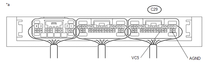
(c) Measure the voltage according to the value(s) in the table below.
 Text in Illustration
|
*a |
Component with harness connected (Certification ECU (Smart Key ECU Assembly)) |
- |
- |
Standard Voltage:
|
Tester Connection |
Condition |
Specified Condition |
|---|---|---|
|
C29-15 (VC5) - C29-12 (AGND) |
Engine switch off, brake pedal not depressed, 30 seconds or more elapsed after driver door opened and then closed |
Below 1 V |
| OK | |
REPLACE ENGINE SWITCH |
| NG | |
REPLACE CERTIFICATION ECU (SMART KEY ECU ASSEMBLY) |
 Engine Immobiliser System Circuit Short to Battery (B279A12)
DESCRIPTION
When the communication line (IMI - EFIO) between the ECM and certification ECU
(smart key ECU assembly) is stuck high, the ECM stores this DTC.
DTC Code
DTC Detec ...
 Security Indicator Light Does not Blink
DESCRIPTION
The certification ECU (smart key ECU assembly) blinks the security indicator
light when the immobiliser is set (engine switch off, or driver door is
opened and closed with ...
Other materials:
Engine does not Start
DESCRIPTION
When the key is in the vehicle and the engine switch is pressed, the certification
ECU (smart key ECU assembly) receives a signal and changes the power source mode.
In addition, when the shift lever is in P or N and the brake pedal is depressed,
the engine can be started by pressi ...
System Description
SYSTEM DESCRIPTION
1. DESCRIPTION
A part-time 2-speed VF2CM transfer uses a touch select 2-4 and high-low
system, enabling the driver to switch between 2WD, H4 and L4 modes by turning
the transfer position switch.
Through these switch signals, the 4 wheel drive control ECU actua ...
Theft deterrent system
Engine immobilizer system
The vehicleŌĆÖs keys have built-in transponder chips that prevent the engine from
starting if the key has not been previously registered in the vehicleŌĆÖs on-board
computer.
Never leave the keys inside the vehicle when you leave the vehicle.
The indicator light fl ...
