Toyota Tacoma (2015-2018) Service Manual: Installation
INSTALLATION
PROCEDURE
1. SET NO. 1 CYLINDER TO TDC/COMPRESSION
.gif)
2. INSTALL CAMSHAFT TIMING GEAR BOLT
NOTICE:
There are different types of camshaft timing gear bolts. Make sure to check the identification mark to determine the tightening torque.
.png)
|
*a |
Identification Mark Stamp |
|
Item |
Identification Mark Stamp |
|
|---|---|---|
|
Intake Side |
Exhaust Side |
|
|
Type A |
A |
B |
|
Type B |
D |
G |
|
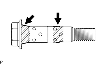
(a) Apply engine oil to the areas of the camshaft timing gear bolt shown in the illustration. |
|
(b) Temporarily install the camshaft timing gear bolt.
Torque:
10 N·m {102 kgf·cm, 7 ft·lbf}
HINT:
Make sure that the flange part of the camshaft timing gear bolt is directly contacting the camshaft timing gear assembly.
(c) Loosen the camshaft timing gear bolt 60 to 180°.
(d) Turn the crankshaft pulley assembly counterclockwise approximately 30 to 90°.
|
(e) Using SST, hold the crankshaft pulley assembly. SST: 09213-54015 91651-60855 SST: 09330-00021 |
|
.png)
(f) Tighten the camshaft timing gear bolt.
Torque:
for Type A :
120 N·m {1224 kgf·cm, 89 ft·lbf}
for Type B :
95 N·m {969 kgf·cm, 70 ft·lbf}
3. INSTALL CAMSHAFT TIMING OIL CONTROL SOLENOID ASSEMBLY
(See page )
4. INSTALL NO. 1 ENGINE UNDER COVER SUB-ASSEMBLY
Torque:
30 N·m {306 kgf·cm, 22 ft·lbf}
5. INSTALL NO. 2 ENGINE UNDER COVER SUB-ASSEMBLY (w/ Off Road Package)
Torque:
30 N·m {306 kgf·cm, 22 ft·lbf}
 Removal
REMOVAL
CAUTION / NOTICE / HINT
NOTICE:
If one of the camshaft timing gear bolts is already removed, do not remove any
other camshaft timing gear bolts.
PROCEDURE
1. REMOVE NO. 2 ENGINE UNDER C ...

Other materials:
Data List / Active Test
DATA LIST / ACTIVE TEST
1. DATA LIST
HINT:
Using the Techstream to read the Data List allows the values or states of switches,
sensors, actuators and other items to be read without removing any parts. This non-intrusive
inspection can be very useful because intermittent conditions or signals ...
Removal
REMOVAL
CAUTION / NOTICE / HINT
CAUTION:
Some of these service operations affect the SRS airbag system. Read the precautionary
notices concerning the SRS airbag system before servicing (See page
).
HINT:
Use the same procedure for both the RH and LH sides.
The procedure describe ...
Inspection
INSPECTION
PROCEDURE
1. INSPECT RADIATOR CORE SUB-ASSEMBLY
Check the core plate for damage.
Text in Illustration
*1
Core Plate
*2
Radiator Core
If the sides of the core plate groove are deformed, it is impossible
to reassem ...
