Toyota Tacoma (2015-2018) Service Manual: Removal
REMOVAL
PROCEDURE
1. PRECAUTION
NOTICE:
After turning the ignition switch off, waiting time may be required before disconnecting the cable from the negative (-) battery terminal.
Therefore, make sure to read the disconnecting the cable from the negative (-) battery terminal notices before proceeding with work.
Click here .gif)
2. DISCONNECT CABLE FROM NEGATIVE BATTERY TERMINAL
NOTICE:
When disconnecting the cable, some systems need to be initialized after the cable is reconnected.
Click here
3. DRAIN BRAKE FLUID
NOTICE:
Immediately wash off any brake fluid that comes into contact with any painted surfaces.
4. REMOVE AIR CLEANER CAP SUB-ASSEMBLY (for 2TR-FE)
Click here
5. REMOVE AIR CLEANER FILTER ELEMENT SUB-ASSEMBLY (for 2TR-FE)
6. REMOVE AIR CLEANER CASE SUB-ASSEMBLY (for 2TR-FE)
Click here
7. REMOVE BRAKE ACTUATOR ASSEMBLY
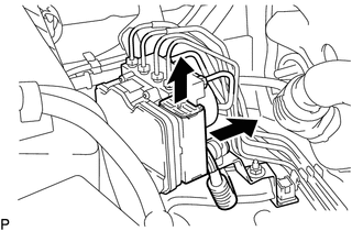
(a) Release the connector lock lever.
(b) Disconnect the brake actuator connector.
|
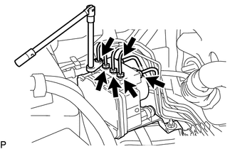
(c) Using a union nut wrench, separate the 6 brake tubes from the brake actuator. |
|
|
(d) Use tags or labels to identify the place to reconnect each brake tube. Text in Illustration
|
|
.png)
|
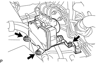
(e) Remove the 3 nuts and brake actuator with bracket. |
|
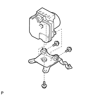
8. REMOVE BRAKE ACTUATOR BRACKET ASSEMBLY
|
(a) Remove the 3 bolts and actuator bracket. |
|
 Installation
INSTALLATION
PROCEDURE
1. INSTALL BRAKE ACTUATOR BRACKET ASSEMBLY
(a) Install the actuator bracket with the 3 bolts in the sequence shown
in the illustration.
Torque:
5.4 N·m ...
 Crawl Switch
Components
COMPONENTS
ILLUSTRATION
Inspection
INSPECTION
PROCEDURE
1. INSPECT CRAWL CONTROL SWITCH (DRIVE MONITOR SWITCH)
(a) Check the resistance.
(1) Measure the resistance according t ...
Other materials:
Removal
REMOVAL
CAUTION / NOTICE / HINT
HINT:
When removing the name plates or stripe tapes, heat the vehicle body or tail
gate and name plates or stripe tapes using a heat light.
Heating Temperature
Item
Temperature
Vehicle Body or Tail Gate
40 to 60 ...
Chassis
General Maintenance
GENERAL MAINTENANCE
PROCEDURE
1. INSPECT STEERING LINKAGE
(a) Check the steering wheel free play (See page
).
(b) Check the steering linkage for looseness or damage.
(1) Check that the tie rod ends do not have excessive play.
(2) Check that the dust seals and boots are ...
Removal
REMOVAL
PROCEDURE
1. REMOVE REAR SEAT CUSHION ASSEMBLY
(a) Remove the 2 bolts and rear seat cushion assembly.
2. REMOVE REAR SEATBACK HINGE COVER
(a) Disengage the 6 claws to remove the 2 rear seatback hinge covers.
...
