Toyota Tacoma (2015-2018) Service Manual: Installation
INSTALLATION
PROCEDURE
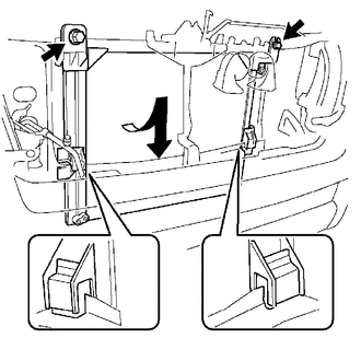
1. INSTALL COOLER CONDENSER ASSEMBLY
(a) Engage the 2 claws to install the 2 condenser upper brackets.
(b) Engage the 2 claws to install the 2 condenser lower brackets.
|
(c) Lift the cooler condenser assembly up from the rear side of the vehicle, and install the condenser lower brackets onto the upper part of the radiator lower supports with the 2 bolts. Torque: 9.0 N·m {92 kgf·cm, 80 in·lbf} |
|
2. INSTALL AIR CONDITIONING TUBE ASSEMBLY
(a) Remove the vinyl tape from the air conditioning tube assembly and connecting part of the cooler condenser assembly.
(b) Apply sufficient compressor oil to a new O-ring and fitting surface of the cooler condenser assembly.
Compressor oil:
PSD1 or equivalent
(c) Install the O-ring to the air conditioning tube assembly.
(d) Install the air conditioning tube assembly to the cooler condenser assembly with the bolt.
Torque:
9.8 N·m {100 kgf·cm, 87 in·lbf}
3. INSTALL DISCHARGE HOSE SUB-ASSEMBLY
(a) Remove the vinyl tape from the discharge hose sub-assembly and connecting part of the cooler condenser assembly.
(b) Apply sufficient compressor oil to a new O-ring and fitting surface of the cooler condenser assembly.
Compressor oil:
PSD1 or equivalent
(c) Install the O-ring to the discharge hose sub-assembly.
(d) Install the discharge hose sub-assembly to the cooler condenser assembly with the bolt.
Torque:
9.8 N·m {100 kgf·cm, 87 in·lbf}
4. INSTALL RADIATOR ASSEMBLY (for 2TR-FE)
Click here .gif)
5. INSTALL RADIATOR ASSEMBLY (for 2GR-FKS)
Click here
6. CONNECT CABLE TO NEGATIVE BATTERY TERMINAL
Torque:
5.4 N·m {55 kgf·cm, 48 in·lbf}
NOTICE:
When disconnecting the cable, some systems need to be initialized after the cable is reconnected.
Click here
7. CHARGE AIR CONDITIONING SYSTEM WITH REFRIGERANT
Click here
8. WARM UP ENGINE
Click here
9. INSPECT FOR REFRIGERANT LEAK
Click here
 Removal
REMOVAL
PROCEDURE
1. PRECAUTION
NOTICE:
After turning the ignition switch off, waiting time may be required before disconnecting
the cable from the negative (-) battery terminal. Therefore, make ...
 Front Blower Motor
Inspection
INSPECTION
PROCEDURE
1. INSPECT BLOWER MOTOR
(a) Inspect the blower motor.
(1) Connect the positive (+) lead from to terminal 1 and negative (-)
lead to terminal 2, ...
Other materials:
Disposal
DISPOSAL
PROCEDURE
1. DISPOSE OF BRAKE BOOSTER ACCUMULATOR ASSEMBLY
(a) Place the brake booster accumulator in a vise and cover it with a cloth.
(b) Slowly cut a hole on the brake booster accumulator side in the A portion
shown in the illustration on the left. And discharge the gas and liqui ...
No Answer-Back
DESCRIPTION
In some cases, wireless door lock control functions are normal but the hazard
warning light and/or wireless door lock buzzer answer-back function(s) does not
operate. In such cases, hazard warning light and wireless door lock buzzer signal
outputs from the main body ECU (multiplex ...
Installation
INSTALLATION
PROCEDURE
1. INSTALL BRAKE PEDAL PAD
(a) Install the brake pedal pad onto the brake pedal.
2. INSTALL BRAKE PEDAL SUPPORT ASSEMBLY
(a) Install the brake pedal support assembly with 4 nuts.
Torque:
14 N·m {145 kgf·cm, 10 ft·lbf}
(b) Connect the stop light switch connector t ...
