Toyota Tacoma (2015-2018) Service Manual: Installation
INSTALLATION
PROCEDURE
1. INSTALL BRAKE ACTUATOR BRACKET ASSEMBLY
|
(a) Install the actuator bracket with the 3 bolts in the sequence shown in the illustration. Torque: 5.4 N·m {55 kgf·cm, 48 in·lbf} |
|
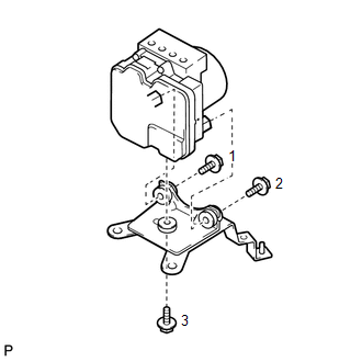
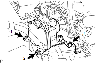
2. INSTALL BRAKE ACTUATOR ASSEMBLY
|
(a) Install the brake actuator with bracket with the 3 nuts in the sequence shown in the illustration. Torque: 19 N·m {194 kgf·cm, 14 ft·lbf} NOTICE:
|
|
|
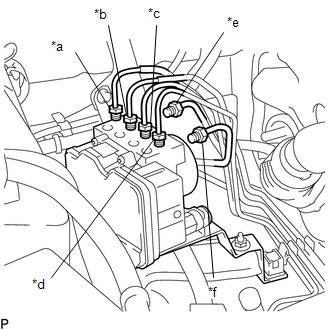
(b) Temporarily install each brake tube in the correct positions of the brake actuator as shown in the illustration. Text in Illustration
|
|
|
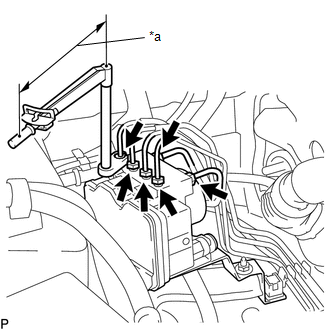
(c) Using a union nut wrench, install the 6 brake tubes to the brake actuator. Text in Illustration
(1) for 12 mm flare nuts : Torque: Specified tightening torque : 20 N·m {199 kgf·cm, 14 ft·lbf} HINT:
(2) for 10 mm flare nuts : Torque: Specified tightening torque : 15 N·m {155 kgf·cm, 11 ft·lbf} HINT:
|
|
(d) Connect the brake actuator connector.
(e) Lock the connector lock lever.
NOTICE:
Make sure that the lever is locked securely.
3. INSTALL AIR CLEANER CASE SUB-ASSEMBLY (for 2TR-FE)
Click here .gif)
4. INSTALL AIR CLEANER FILTER ELEMENT SUB-ASSEMBLY (for 2TR-FE)
5. INSTALL AIR CLEANER CAP SUB-ASSEMBLY (for 2TR-FE)
Click here
6. CONNECT CABLE TO NEGATIVE BATTERY TERMINAL
Torque:
5.4 N·m {55 kgf·cm, 48 in·lbf}
NOTICE:
When disconnecting the cable, some systems need to be initialized after the cable is reconnected.
Click here
7. FILL RESERVOIR WITH BRAKE FLUID
Click here
8. BLEED MASTER CYLINDER
Click here
9. BLEED BRAKE LINE
Click here
10. BLEED BRAKE ACTUATOR
Click here
11. INSPECT FLUID LEVEL IN RESERVOIR
Click here
12. INSPECT FOR BRAKE FLUID LEAK
13. CHECK BRAKE ACTUATOR WITH TECHSTREAM
Click here
14. PERFORM YAW RATE AND ACCELERATION SENSOR ZERO POINT CALIBRATION
Click here
15. CHECK AND CLEAR DTC
Click here
 On-vehicle Inspection
ON-VEHICLE INSPECTION
PROCEDURE
1. CONNECT TECHSTREAM
(a) Warm up the engine.
(b) Turn the ignition switch to off.
(c) Connect the Techstream to the DLC3.
(d) Turn the ignition switch to ON.
(e ...
 Removal
REMOVAL
PROCEDURE
1. PRECAUTION
NOTICE:
After turning the ignition switch off, waiting time may be required before disconnecting
the cable from the negative (-) battery terminal.
Therefore, mak ...
Other materials:
Problem Symptoms Table
PROBLEM SYMPTOMS TABLE
HINT:
Use the table below to help determine the cause of problem symptoms. If multiple
suspected areas are listed, the potential causes of the symptoms are listed in order
of probability in the "Suspected Area" column of the table. Check each symptom by
check ...
Back-up Power Source Circuit
DESCRIPTION
The back-up power source circuit for the air conditioning amplifier assembly
is shown below. Power is supplied even when the ignition switch is off. The power
is used for diagnostic trouble code memory, etc.
WIRING DIAGRAM
CAUTION / NOTICE / HINT
NOTICE:
Inspect the fuses for ...
On-vehicle Inspection
ON-VEHICLE INSPECTION
PROCEDURE
1. INSPECT BRAKE MASTER CYLINDER FLUID PRESSURE CHANGE
(a) Inspect the battery positive voltage.
Battery positive voltage:
10 to 14 V
(b) Turn the ignition switch to OFF, and depress the brake pedal more than 20
times.
HINT:
When pressure in the accumulator ...
