Toyota Tacoma (2015-2018) Service Manual: Disassembly
DISASSEMBLY
PROCEDURE
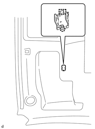
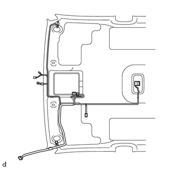
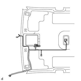
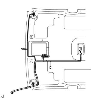
1. REMOVE TELEPHONE MICROPHONE ASSEMBLY
Click here .gif)
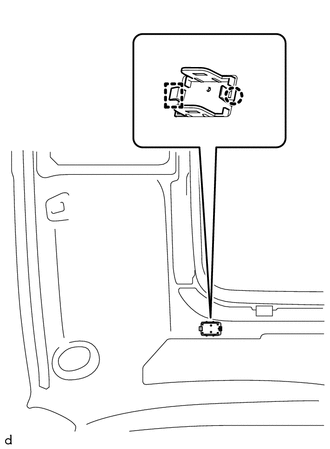
2. REMOVE MICROPHONE CASE
|
(a) w/o Sliding Roof: (1) Disengage the claw and guide to remove the microphone case. |
|
|
(b) w/ Sliding Roof: (1) Disengage the claw and guide to remove the microphone case. |
|
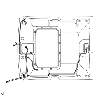
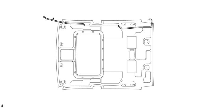
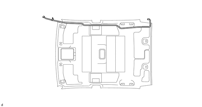
3. REMOVE NO. 1 ROOF WIRE (w/ Sliding Roof)
(a) w/ Vanity Light:
|
(1) w/ EC Mirror:
|
|

|
(2) w/o EC Mirror:
|
|
(b) w/o Vanity Light:
|
(1) w/ EC Mirror:
|
|
|
(2) w/o EC Mirror:
|
|

(c) w/o Toyota Safety Sense P:
|
(1) Remove the No. 1 roof wire. |
|

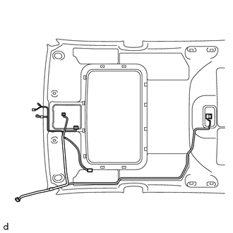
4. REMOVE NO. 1 ROOF WIRE (w/o Sliding Roof)
(a) w/ Vanity Light:
|
(1) w/ EC Mirror:
|
|
|
(2) w/o EC Mirror:
|
|

(b) w/o Vanity Light:
|
(1) w/ EC Mirror:
|
|

|
(2) w/o EC Mirror:
|
|
(c) w/o Toyota Safety Sense P:
|
(1) Remove the No. 1 roof wire. |
|
5. REMOVE NO. 2 ANTENNA CORD SUB-ASSEMBLY (w/ Sliding Roof)
(a) Remove the No. 2 antenna cord sub-assembly.
6. REMOVE NO. 2 ANTENNA CORD SUB-ASSEMBLY (w/o Sliding Roof)
(a) Remove the No. 2 antenna cord sub-assembly.
 Components
COMPONENTS
ILLUSTRATION
*A
w/o Woofer
*B
w/ Woofer
*1
LUGGAGE COMPARTMENT SIDE TRAY LH
*2
LUGGAGE COMP ...
 Installation
INSTALLATION
PROCEDURE
1. INSTALL ROOF HEADLINING ASSEMBLY
(a) Insert the roof headlining assembly into the vehicle from the front
door RH side.
NOTICE:
Check that ...
Other materials:
Parking Brake System
Adjustment
ADJUSTMENT
PROCEDURE
1. INSPECT PARKING BRAKE LEVER TRAVEL
(a) Fully pull the parking brake lever to engage the parking brake.
(b) Release the lever to disengage the parking brake.
(c) Slowly pull the parking brake lever all the way and count the number of clicks.
Standard parkin ...
Turn Signal Switch Circuit
DESCRIPTION
The combination meter assembly receives the turn signal switch information and
controls the turn signal lights.
WIRING DIAGRAM
PROCEDURE
1.
READ VALUE USING TECHSTREAM (TURN SIGNAL SWITCH)
(a) Connect the Techstream to the DLC3.
(b) Turn the igni ...
Terminals Of Ecm
TERMINALS OF ECM
HINT:
The standard normal voltage between each pair of ECM terminals is shown in the
table below. The appropriate conditions for checking each pair of terminals are
also indicated. The result of checks should be compared with the standard normal
voltage for that pair of te ...
