Toyota Tacoma (2015-2018) Service Manual: Removal
REMOVAL
PROCEDURE
1. REMOVE REAR WHEEL
2. DRAIN BRAKE FLUID
HINT:
Immediately wash off any brake fluid that comes into contact with any painted surfaces.
3. REMOVE REAR BRAKE DRUM SUB-ASSEMBLY
(a) Release the parking brake, and remove the rear brake drum.
If the rear brake drum cannot be removed easily, perform the following procedures.
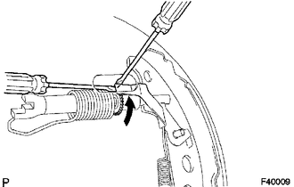
(b) Remove the hole plug and insert a screwdriver through the hole into the backing plate, and hold the automatic adjusting lever away from the adjuster.
(c) Using another screwdriver, contract the brake shoe by turning the adjusting bolt.
(d) Remove the drum gasket from the rear brake drum.
 Disassembly
DISASSEMBLY
PROCEDURE
1. REMOVE FRONT BRAKE SHOE
(a) Using SST, remove the shoe return spring from the front brake shoe.
SST: 09921-00010
(b) Using needle-nose pliers, remove the ret ...
 Inspection
INSPECTION
PROCEDURE
1. INSPECT BRAKE DRUM INSIDE DIAMETER
(a) Using a brake drum gauge or equivalent, measure the inside diameter of the
drum.
Standard inside diameter:
254 mm (10.00 in.)
...
Other materials:
Components
COMPONENTS
ILLUSTRATION
ILLUSTRATION
ILLUSTRATION
ILLUSTRATION
...
If your vehicle overheats
The following may indicate that your vehicle is overheating.
● The needle of the engine coolant temperature gauge (→P. 155) enters the red
zone or a loss of engine power is experienced.
(For example, the vehicle speed does not increase.) ● Steam comes out from under
the hood. ...
Road Test
ROAD TEST
1. PROBLEM SYMPTOM CONFIRMATION
(a) Based on the result of the customer problem analysis, try to reproduce the
symptoms. If the problem is that the transmission does not shift up or down, or
that the shift point is too high or too low, conduct the following road test referring
to t ...
