Toyota Tacoma (2015-2018) Service Manual: Inspection
INSPECTION
PROCEDURE
1. INSPECT BRAKE DRUM INSIDE DIAMETER
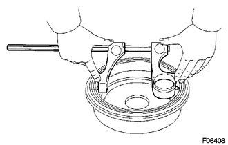
(a) Using a brake drum gauge or equivalent, measure the inside diameter of the drum.
Standard inside diameter:
254 mm (10.00 in.)
Maximum inside diameter:
256 mm (10.08 in.)
If the inside diameter is greater than the maximum, replace the brake drum.
2. INSPECT REAR DRUM BRAKE SHOE LINING THICKNESS
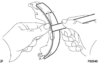
(a) Using a ruler, measure the thickness of the shoe lining.
Standard thickness:
5.0 mm (0.197 in.)
Minimum thickness:
1.0 mm (0.0394 in.)
If the lining thickness is the minimum value or less, or if there is any severe or uneven wear, replace the brake shoe.
3. INSPECT BRAKE DRUM AND REAR DRUM BRAKE SHOE LINING FOR PROPER CONTACT
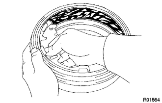
(a) Apply chalk to the inside surface of the drum, then grind the brake shoe lining for proper fitting.
If the contact between the drum and the shoe lining is improper, repair it using a brake shoe grinder or replace the brake shoe assembly.
4. INSPECT REAR WHEEL BRAKE CYLINDER
(a) Check the cylinder bore and piston for rust and scoring.
 Removal
REMOVAL
PROCEDURE
1. REMOVE REAR WHEEL
2. DRAIN BRAKE FLUID
HINT:
Immediately wash off any brake fluid that comes into contact with any painted
surfaces.
3. REMOVE REAR BRAKE DRUM SUB-ASSEMBLY ...
 Reassembly
REASSEMBLY
PROCEDURE
1. INSTALL REAR WHEEL CYLINDER CUP KIT
(a) Provisionally tighten the bleeder plug to the rear wheel brake cylinder,
and install the bleeder plug cap.
(b) Apply lithium soa ...
Other materials:
Diagnostic Trouble Code Chart
DIAGNOSTIC TROUBLE CODE CHART
HINT:
If a trouble code is displayed during the DTC check, inspect the trouble areas
listed for that code. For details of the code, refer to the "See page" below.
Seat Heater System
DTC Code
Detection Item
See page
...
Disassembly
DISASSEMBLY
PROCEDURE
1. REMOVE GENERATOR PULLEY
(a) Mount the generator assembly in the vise between aluminum plates.
NOTICE:
Do not overtighten the vise.
(b) Install SST 1-A to the generator pulley shaft.
Text in Illustration
*a
Hold
Turn
...
Meter Illumination does not Dim at Night
DESCRIPTION
In this circuit, the combination meter assembly auto dimmer signals from the
main body ECU using the CAN communication system (CAN V1 Bus). When the combination
meter assembly an auto dimmer signal, it dims the meter illumination (warning and
indicator lights). The main body ECU ( ...
