Toyota Tacoma (2015-2018) Service Manual: ACC Monitor Malfunction (B2274)
DESCRIPTION
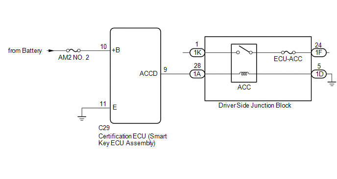
This DTC is stored when a malfunction in the ACC output circuit is detected. The ACC output circuit is the circuit that goes from the ACC output terminal of the certification ECU (smart key ECU assembly) to the ACC relay.
HINT:
When the cable is disconnected and reconnected to the negative (-) battery terminal, the power source mode returns to the state it was in before the cable was disconnected.
|
DTC Code |
DTC Detection Condition |
Trouble Area |
DTC Output Confirmation Operation |
|---|---|---|---|
|
B2274 |
Malfunction in the ACC relay circuit in the certification ECU (smart key ECU assembly) or in the external circuit (1-trip detection logic*). HINT: When the voltage at terminal ACCD is not at the standard, the system is determined to be malfunctioning. |
|
Wait 10 seconds after turning the engine switch on (ACC) or on (IG), and then wait another 10 seconds after turning the engine switch off. |
- *: Only detected while a malfunction is present.
|
Vehicle Condition when Malfunction Detected |
Fail-safe Function when Malfunction Detected |
|---|---|
HINT: The engine switch can be turned on (IG) and the engine can be started. |
- |
WIRING DIAGRAM
CAUTION / NOTICE / HINT
NOTICE:
- When using the Techstream with the engine switch off, connect the Techstream to the DLC3 and turn a courtesy light switch on and off at intervals of 1.5 seconds or less until communication between the Techstream and the vehicle begins. Then select the vehicle type under manual mode and enter the following menus: Body Electrical / Smart Key. While using the Techstream, periodically turn a courtesy light switch on and off at intervals of 1.5 seconds or less to maintain communication between the Techstream and the vehicle.
- The smart key system (for Start Function) uses a multiplex communication
system (LIN communication system) and the CAN communication system. Inspect
the communication function by following How to Proceed with Troubleshooting.
Click here
.gif)
Troubleshoot the smart key system (for Start Function) after confirming that the communication systems are functioning properly.
- Before replacing the certification ECU (smart key ECU assembly), refer
to the smart key system (for Start Function) precaution (See page
).
- Inspect the fuses of circuits related to this system before performing the following inspection procedure.
- After performing repairs, perform the operation that fulfills the DTC output confirmation operation, and then confirm that no DTCs are output again.
|
DTC |
Data List Item |
Active Test Item |
|---|---|---|
|
B2274 |
Power Source Control
Starting Control
|
- |
PROCEDURE
|
1. |
CHECK HARNESS AND CONNECTOR (POWER SOURCE) |
| NG | .gif) |
REPAIR OR REPLACE HARNESS ORCONNECTOR IN CIRCUIT CONNECTED TOPOWER SOURCE |
|
.gif)
|
2. |
CHECK HARNESS AND CONNECTOR (GROUND) |
| NG | |
REPAIR OR REPLACE HARNESS OR CONNECTOR |
|
|
3. |
CHECK HARNESS AND CONNECTOR (CERTIFICATION ECU (SMART KEY ECUASSEMBLY) - DRIVER SIDE JUNCTION BLOCK) |
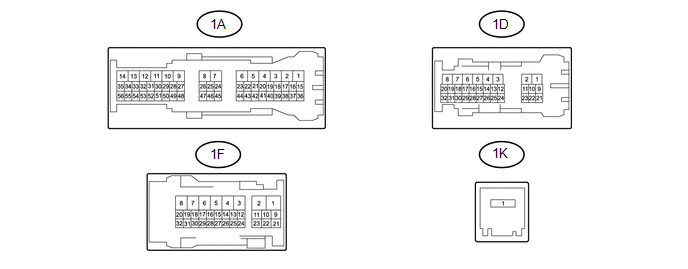
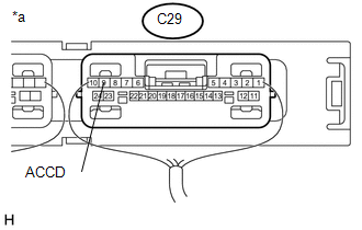
(a) Disconnect the C29 connector from the certification ECU (smart key ECU assembly).
(b) Disconnect the connector from the driver side junction block.
(c) Measure the resistance according to the value(s) in the table below.
Standard Resistance:
|
Tester Connection |
Condition |
Specified Condition |
|---|---|---|
|
C29-9 (ACCD) - 1A-28 |
Always |
Below 1 Ω |
|
1D-5 - Body ground |
Always |
Below 1 Ω |
|
C29-9 (ACCD) or 1A-28 - Body ground |
Always |
10 kΩ or higher |
| NG | |
REPAIR OR REPLACE HARNESS OR CONNECTOR |
|
|
4. |
CHECK DRIVER SIDE JUNCTION BLOCK (ACC RELAY) |
(a) Remove the driver side junction block. (See page
)
 Text in Illustration
|
*a |
Component without harness connected (Driver Side Junction Block) |
- |
- |
(b) Remove the main body ECU (multiplex network body ECU) from the driver side
junction block. (See page )
(c) Measure the resistance according to the value(s) in the table below.
Standard Resistance:
|
Tester Connection |
Condition |
Specified Condition |
|---|---|---|
|
1K-1 - 1F-24 |
Battery voltage not applied to terminals 1A - 28 and 1D-5 |
10 kΩ or higher |
|
Battery voltage applied to terminals 1A - 28 and 1D-5 |
Below 1 Ω |
| NG | |
REPLACE DRIVER SIDE JUNCTION BLOCK |
|
|
5. |
INSPECT CERTIFICATION ECU (SMART KEY ECU ASSEMBLY) |
(a) Reconnect the certification ECU (smart key ECU assembly) connector.
|
(b) Measure the voltage according to the value(s) in the table below. Standard Voltage:
|
|
| OK | |
USE SIMULATION METHOD TO CHECK |
| NG | |
REPLACE CERTIFICATION ECU (SMART KEY ECU ASSEMBLY) |
 Ignition Hold Monitor Malfunction (B2271)
DESCRIPTION
This DTC is stored when a malfunction in the IG circuit or IG hold circuit in
the certification ECU (smart key ECU assembly) is detected.
HINT:
When the cable is disconnected and reco ...
 Engine does not Start
DESCRIPTION
When the key is in the vehicle and the engine switch is pressed, the certification
ECU (smart key ECU assembly) receives a signal and changes the power source mode.
In addition, when ...
Other materials:
Fail-safe Chart
FAIL-SAFE CHART
If any of the following DTCs are stored, the ECM enters fail-safe mode to allow
the vehicle to be driven temporarily.
DTC
Fail-safe Operation
Fail-safe Deactivation Condition
P161A87
Generator command is maintained
...
Inspection
INSPECTION
PROCEDURE
1. INSPECT FRONT SHOCK ABSORBER ASSEMBLY
(a) Compress and extend the shock absorber rod and check that there is no abnormal
resistance or unusual sound during operation.
If there is any abnormality, replace the front shock absorber with a new one.
NOTICE:
When disposin ...
Replacement
REPLACEMENT
PROCEDURE
1. REPLACE STRAIGHT PIN
NOTICE:
It is not necessary to remove the straight pin unless it is being replaced.
(a) Using a plastic-faced hammer, tap in new straight pins to the cylinder block.
Text in Illustration
*A
Front Side
*B
...
