Toyota Tacoma (2015-2018) Service Manual: Removal
REMOVAL
CAUTION / NOTICE / HINT
NOTICE:
Release the vacuum from booster by depressing the brake pedal several times.
Then remove the brake master cylinder from brake booster.
PROCEDURE
1. PRECAUTION
NOTICE:
After turning the ignition switch off, waiting time may be required before disconnecting the cable from the negative (-) battery terminal. Therefore, make sure to read the disconnecting the cable from the negative (-) battery terminal notices before proceeding with work.
Click here .gif)
2. DISCONNECT CABLE FROM NEGATIVE BATTERY TERMINAL
NOTICE:
When disconnecting the cable, some systems need to be initialized after the cable is reconnected.
Click here
3. DRAIN BRAKE FLUID
NOTICE:
Immediately wash off any brake fluid that comes into contact with any painted surfaces.
4. REMOVE CLUTCH RESERVOIR TUBE (for Manual Transmission)
|
(a) Disconnect the clutch reservoir tube from the reservoir. |
|
5. REMOVE BRAKE MASTER CYLINDER SUB-ASSEMBLY
|
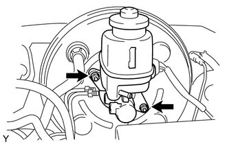
(a) Disconnect the brake fluid level warning switch connector. |
|
|
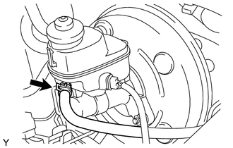
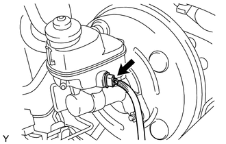
(b) Using a union nut wrench, disconnect the 2 brake lines from the brake master cylinder sub-assembly. |
|
.png)
|
(c) Remove the 2 nuts, and then pull the brake master cylinder sub-assembly out of the brake booster. |
|
(d) Remove the O-ring from the brake master cylinder sub-assembly.
NOTICE:
- The master cylinder requires careful handling. Do not allow the master cylinder to receive any impact, such as from being dropped. Do not reuse a master cylinder that has been dropped.
- Do not strike or pinch the master cylinder piston, and do not cause any damage to the master cylinder piston by any other means.
- Release the vacuum from booster by depressing the brake pedal several
times.
Then remove the brake master cylinder from brake booster.
- When installing the brake master cylinder sub-assembly onto the brake booster, or when removing the brake master cylinder sub-assembly from the brake booster, make sure that the brake master cylinder sub-assembly is kept horizontal or its tip faces downward (the piston faces upward) to prevent the master cylinder piston from falling off.
- Do not allow any foreign objects to contaminate the master cylinder piston. If a foreign object gets on the piston, remove it by using a piece of cloth and then apply an even layer of lithium soap based glycol grease around the circumference (sliding part) of the piston.
- Do not use any other type of grease or fluid.
 Disassembly
DISASSEMBLY
PROCEDURE
1. REMOVE BRAKE MASTER CYLINDER RESERVOIR FILLER CAP ASSEMBLY
2. REMOVE BRAKE MASTER CYLINDER RESERVOIR STRAINER
3. REMOVE BRAKE MASTER CYLINDER RESERVOIR ASSEMBLY
(a) Fix t ...
 Installation
INSTALLATION
PROCEDURE
1. INSPECT AND ADJUST BRAKE BOOSTER PUSH ROD
NOTICE:
The brake booster interior must not be a vacuum when adjusting the booster. Stop
the engine and depress the brake peda ...
Other materials:
Precaution
PRECAUTION
1. INITIALIZATION
NOTICE:
If the ECM is replaced, register the ECU communication ID for Engine
Immobiliser System (See page ).
Perform Registration (VIN registration) when replacing the ECM (See
page ).
HINT:
The engine learned value cannot be rese ...
Fuel Pump Ecu
Components
COMPONENTS
ILLUSTRATION
Removal
REMOVAL
PROCEDURE
1. PRECAUTION
NOTICE:
After turning the ignition switch off, waiting time may be required before disconnecting
the cable from the battery terminal. Therefore, make sure to read the disconnecting
the cable from the battery ...
Data List / Active Test
DATA LIST / ACTIVE TEST
1. DATA LIST
HINT:
Using the Techstream to read the Data List allows the values or states of switches,
sensors, actuators and other items to be read without removing any parts. This non-intrusive
inspection can be very useful because intermittent conditions or signals ...
