Toyota Tacoma (2015-2018) Service Manual: Reassembly
REASSEMBLY
PROCEDURE
1. TEMPORARILY TIGHTEN FRONT DISC BRAKE BLEEDER PLUG
(a) Provisionally tighten the bleeder plug to the disc brake cylinder.
(b) Install the bleeder plug cap onto the bleeder plug.
2. INSTALL PISTON SEAL
|
(a) Apply lithium soap base glycol grease to 4 new piston seals. |
|
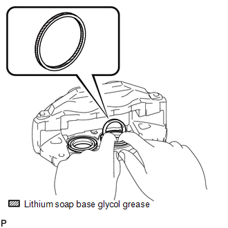
(b) Install the 4 piston seals onto the disc brake cylinder.
3. INSTALL FRONT DISC BRAKE PISTON
|
(a) Apply lithium soap base glycol grease to the 4 disc brake pistons and a new 4 cylinder boots. |
|
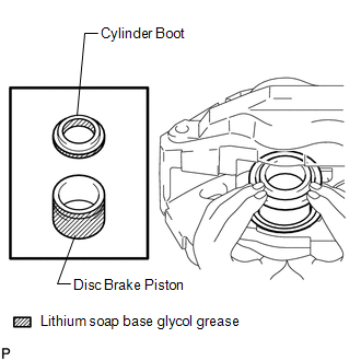
(b) Install the 4 disc brake pistons onto the disc brake cylinder.
NOTICE:
Do not install the disc brake piston into the disc brake cylinder forcibly.
4. INSTALL CYLINDER BOOT
|
(a) Install the 4 cylinder boots onto the disc brake cylinder. HINT: Install the cylinder boot securely onto the grooves of the disc brake cylinder and piston. |
|
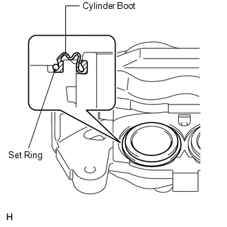
(b) Install the 4 cylinder boot set rings.
 Installation
INSTALLATION
PROCEDURE
1. INSTALL FRONT DISC
(a) Align the matchmarks of the front disc and the front axle hub and
install the front disc.
Text in Illustration
...

Other materials:
Removal
REMOVAL
PROCEDURE
1. REMOVE SHIFT LEVER KNOB SUB-ASSEMBLY (for Automatic Transmission)
(a) Using a molding remover A, disengage the 2 claws to separate the
shifting hole cover sub-assembly.
(b) Rotate the shift lever knob sub-as ...
Check Bus 5 Lines for Short Circuit
DESCRIPTION
There may be a short circuit between the CAN main bus lines and/or CAN branch
lines when the resistance between terminals 15 (CA5H) and 16 (CA5L) of the central
gateway ECU (network gateway ECU) is below 54 Ω.
Detection Item
Trouble Area
Resi ...
TS and CG Terminal Circuit
DESCRIPTION
In Test Mode (signal check), a malfunction in the speed sensor that cannot be
detected when the vehicle is stopped can be detected while driving.
Sensor check mode can be entered by connecting terminals TS and CG of the DLC3
and turning the ignition switch from off to ON.
WIRING D ...
