DISASSEMBLY
PROCEDURE
1. REMOVE BRAKE MASTER CYLINDER RESERVOIR FILLER CAP ASSEMBLY
2. REMOVE BRAKE MASTER CYLINDER RESERVOIR STRAINER
3. REMOVE BRAKE MASTER CYLINDER RESERVOIR ASSEMBLY
(a) Fix the brake master cylinder in a vise between aluminum plates.
NOTICE:
Do not overtighten the vise.
|
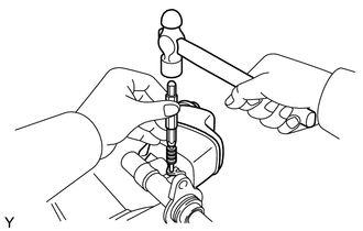
(b) Using a pin punch and a hammer, tap out the straight pin and remove the brake master cylinder reservoir. |
|
4. REMOVE MASTER CYLINDER RESERVOIR GROMMET
(a) Remove the 2 grommets from the master cylinder reservoir.
Components
RemovalData Signal Circuit between Radio Receiver and Extension Module
DESCRIPTION
The stereo component tuner assembly sends the image data signal to the radio
and display receiver assembly via this circuit.
WIRING DIAGRAM
PROCEDURE
1.
CHECK NO. 1 NAVIGATION WIRE
(a) Disconnect the R33 radio and display receiver assembly connect ...
Removal
REMOVAL
PROCEDURE
1. REMOVE LOWER INSTRUMENT PANEL FINISH PANEL SUB-ASSEMBLY RH
(See page )
2. REMOVE LOWER INSTRUMENT PANEL ASSEMBLY
(See page )
3. REMOVE AIR CONDITIONING CONTROL ASSEMBLY
(a) for Automatic Air Conditioning System (See page
)
(b) for Manual Air Conditioning System (Se ...
Front Occupant Classification Sensor LH Collision Detection (B1785)
DESCRIPTION
DTC B1785 is set when the occupant detection ECU receives a collision detection
signal, which is sent by the occupant classification sensor front LH when an accident
occurs.
DTC B1785 is also set when the front seat with adjuster frame assembly RH is
subjected to a strong impact, ...