Toyota Tacoma (2015-2018) Service Manual: Removal
REMOVAL
PROCEDURE
1. PRECAUTION
CAUTION:
Be sure to read Precaution thoroughly before servicing (See page
.gif) ).
).
NOTICE:
After turning the ignition switch off, waiting time may be required before disconnecting the cable from the negative (-) battery terminal. Therefore, make sure to read the disconnecting the cable from the negative (-) battery terminal notices before proceeding with work.
Click here
2. DISCONNECT CABLE FROM NEGATIVE BATTERY TERMINAL
CAUTION:
Wait at least 90 seconds after disconnecting the cable from the negative (-) battery terminal to disable the SRS system.
NOTICE:
When disconnecting the cable, some systems need to be initialized after the cable is reconnected.
Click here
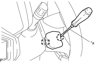
3. REMOVE LOWER NO. 3 STEERING WHEEL COVER
|
(a) Using a screwdriver with its tip wrapped in protective tape, disengage the claw and guide to remove the lower No. 3 steering wheel cover. Text in Illustration
|
|
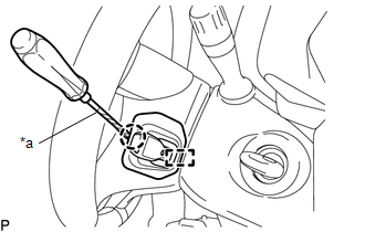
4. REMOVE LOWER NO. 2 STEERING WHEEL COVER
|
(a) Using a screwdriver with its tip wrapped in protective tape, disengage the claw and guide to remove the lower No. 2 steering wheel cover. Text in Illustration
|
|
5. REMOVE STEERING PAD
CAUTION:
When storing the steering pad, keep the airbag deployment side facing upward.
(a) Check that the ignition switch is off.
(b) Check that the cable is disconnected from the negative (-) battery terminal.
NOTICE:
Wait at least 90 seconds after disconnecting the cable from the negative (-) battery terminal to disable the SRS system.
|
(c) Using a T30 "TORX" socket wrench, loosen the 2 screws until the groove along the screw circumference catches on the screw case. |
|
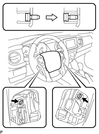
(d) Pull the steering pad toward you.
|
(e) Using a screwdriver with its tip wrapped in protective tape, release the 2 airbag connector locks. Text in Illustration
|
|
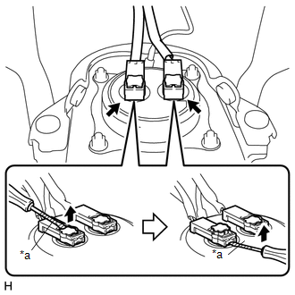
(f) Disconnect the 2 airbag connectors.
NOTICE:
When disconnecting any airbag connector, take care not to damage the airbag wire harness.
(g) Disconnect the horn terminal to remove the steering pad.
 On-vehicle Inspection
ON-VEHICLE INSPECTION
PROCEDURE
1. INSPECT STEERING PAD (for Vehicle not Involved in Collision)
(a) Perform a diagnostic system check (See page
).
(b) With the steering pad installed on the vehi ...
 Installation
INSTALLATION
PROCEDURE
1. INSTALL STEERING PAD
(a) Check that the ignition switch is off.
(b) Check that the cable is disconnected from the negative (-) battery terminal.
CAUTION:
Wait at least ...
Other materials:
Adjustment
ADJUSTMENT
PROCEDURE
1. ADJUST PARK/NEUTRAL POSITION SWITCH
(a) While pushing the shift lock release button, move the shift lever to N.
(b) Remove the bolt of the park/neutral position switch.
(c) Clean the bolt and bolt hole.
(d) Apply adhesive to 2 or 3 threads on the end of the bolt.
Adhes ...
System Description
SYSTEM DESCRIPTION
1. POWER DOOR LOCK CONTROL SYSTEM DESCRIPTION
(a) The power door lock system locks/unlocks all the doors.
The main body ECU (multiplex network body ECU) receives lock/unlock request signals
from a door control switch or the driver door key lock and unlock switch. Then,
the ...
Other System Malfunction (C1A63)
DESCRIPTION
The millimeter wave radar sensor assembly receives accelerator pedal position
sensor signals from the ECM to determine if the accelerator pedal is being depressed.
If the ECM detects a malfunction in the accelerator pedal position sensor or SFI
system, the millimeter wave radar se ...
