Toyota Tacoma (2015-2018) Service Manual: Parts Location
PARTS LOCATION
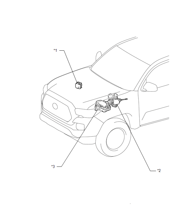
ILLUSTRATION
|
*A |
for Vacuum Brake Booster |
*B |
for Hydraulic Brake Booster |
|
*1 |
BRAKE ACTUATOR ASSEMBLY (SKID CONTROL ECU) |
*2 |
BRAKE BOOSTER WITH MASTER CYLINDER ASSEMBLY (SKID CONTROL ECU) |
|
*3 |
ENGINE ROOM RELAY BLOCK - ECU-B NO. 1 FUSE - ECU-B NO. 3 FUSE |
- |
- |
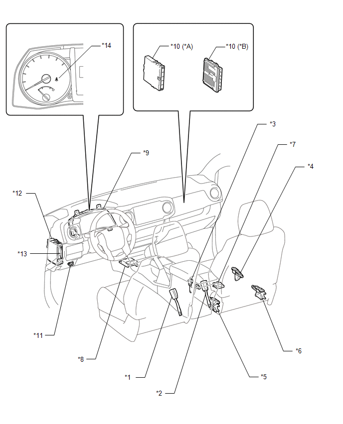
ILLUSTRATION
|
*A |
for 2TR-FE |
*B |
for 2GR-FKS |
|
*1 |
FRONT SEAT INNER BELT ASSEMBLY LH |
*2 |
FRONT SEAT INNER BELT ASSEMBLY RH |
|
*3 |
FRONT OCCUPANT CLASSIFICATION SENSOR LH |
*4 |
FRONT OCCUPANT CLASSIFICATION SENSOR RH |
|
*5 |
REAR OCCUPANT CLASSIFICATION SENSOR LH |
*6 |
REAR OCCUPANT CLASSIFICATION SENSOR RH |
|
*7 |
OCCUPANT CLASSIFICATION ECU |
*8 |
AIRBAG SENSOR ASSEMBLY |
|
*9 |
COMBINATION METER ASSEMBLY |
*10 |
ECM |
|
*11 |
DLC3 |
*12 |
DRIVER SIDE JUNCTION BLOCK - METER FUSE - A/BAG-IG2 FUSE |
|
*13 |
MAIN BODY ECU (MULTIPLEX NETWORK BODY ECU) |
*14 |
SEAT BELT WARNING LIGHT |

 Precaution
PRECAUTION
1. IGNITION SWITCH EXPRESSIONS
(a) The type of ignition switch used on this model differs according to the specifications
of the vehicle. The expressions listed in the table below are u ...
Other materials:
Removal
REMOVAL
PROCEDURE
1. REMOVE FUEL TANK ASSEMBLY
Click here
2. DISCONNECT CHARCOAL CANISTER FUEL HOSE
(a) Loosen the hose clip and disconnect the charcoal canister fuel hose.
3. DISCONNECT FUEL TANK VENT HOSE
(a) Push the fuel tank vent hos ...
Removal
REMOVAL
PROCEDURE
1. REMOVE FRONT DOOR SCUFF PLATE LH
for Double Cab:
Click here
for Access Cab:
Click here
2. REMOVE COWL SIDE TRIM BOARD LH
Click here
3. REMOVE INSTRUMENT CLUSTER CENTER FINISH PANEL SUB-ASSEMBLY
Click here
4. REMOVE INSTRUMENT CLUSTER FINISH PANEL ASSEMBLY
Cli ...
Key Reminder Buzzer does not Sound
DESCRIPTION
The key reminder warning buzzer sounds when the driver side door is opened while
the ignition switch is in the LOCK or ACC positions. The key reminder warning buzzer
is activated when the main body ECU (multiplex network body ECU) sends a key switch
signal and driver side courtesy ...
