Toyota Tacoma (2015-2018) Service Manual: Disassembly
DISASSEMBLY
PROCEDURE
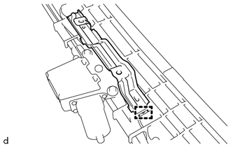
1. REMOVE ROOM LIGHT BRACKET
|
(a) Disengage the guide to remove the room light bracket. |
|
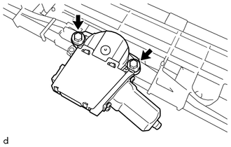
2. REMOVE SLIDING ROOF DRIVE GEAR SUB-ASSEMBLY
|
(a) Remove the 2 bolts and sliding roof drive gear sub-assembly. |
|
3. REMOVE SUNSHADE TRIM SUB-ASSEMBLY
|
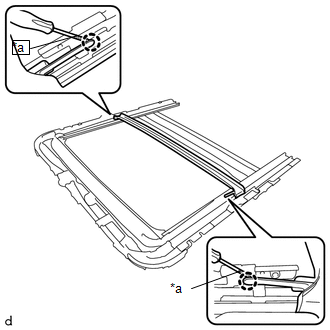
(a) Remove the screw. |
|
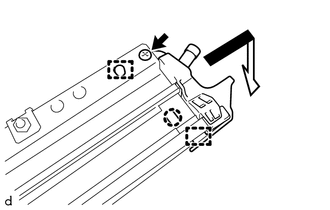
(b) Disengage the claw and 2 guides to remove the sliding roof drain hose joint LH as shown in the illustration.
|
(c) Remove the screw. |
|
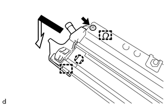
(d) Disengage the claw and 2 guides to remove the sliding roof drain hose joint RH as shown in the illustration.
|
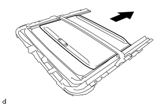
(e) Slide and remove the sunshade trim sub-assembly as shown in the illustration. |
|
4. REMOVE ROOF DRIP CHANNEL
|
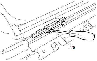
(a) Using a screwdriver with its tip wrapped in protective tape, disengage the 2 claws. Text in Illustration
|
|
|
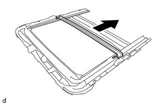
(b) Slide and remove the roof drip channel as shown in the illustration. |
|
5. REMOVE SLIDING ROOF DRIVE CABLE SUB-ASSEMBLY LH
NOTICE:
Do not disassemble the sliding roof drive cable sub-assembly except when replacing it.
|
(a) Using a screwdriver with its tip wrapped in protective tape, disengage the 2 claws to remove the sliding roof guide block. Text in Illustration
|
|
(b) Remove the sliding roof drive cable sub-assembly LH.
6. REMOVE SLIDING ROOF DRIVE CABLE SUB-ASSEMBLY RH
HINT:
Use the same procedure as for the LH side.
 Components
COMPONENTS
ILLUSTRATION
ILLUSTRATION
ILLUSTRATION
...
 Removal
REMOVAL
PROCEDURE
1. REMOVE SLIDING ROOF SIDE GARNISH LH
(a) Fully open the sunshade trim sub-assembly.
(b) Remove the sliding roof side garnish LH.
...
Other materials:
Customize Parameters
CUSTOMIZE PARAMETERS
1. CUSTOMIZING FUNCTION WITH TECHSTREAM
NOTICE:
When the customer requests a change in a function, first make sure that
the function can be customized.
Be sure to make a note of the current settings before customizing.
When troubleshooting a function, f ...
How To Proceed With Troubleshooting
CAUTION / NOTICE / HINT
HINT:
The vehicle stability control system troubleshooting procedures are
based on the premise that the CAN communication system is functioning normally.
Check the CAN communication system first before troubleshooting the vehicle
stability control system ...
Removal
REMOVAL
PROCEDURE
1. REMOVE FRONT FENDER SEAL RH
HINT:
Use the same procedure as for the LH side (See page
).
2. REMOVE V-BANK COVER SUB-ASSEMBLY
3. REMOVE AIR CLEANER CAP AND HOSE
4. REMOVE ENGINE OIL LEVEL DIPSTICK GUIDE
(a) Remove the engine oil level dipstick.
(b) Di ...
