Toyota Tacoma (2015-2018) Service Manual: Removal
REMOVAL
CAUTION / NOTICE / HINT
HINT:
- Use the same procedure for both the RH and LH sides.
- The procedure described below is for the LH side.
PROCEDURE
1. PRECAUTION
CAUTION:
Be sure to read Precaution thoroughly before servicing (See page
.gif) ).
).
NOTICE:
After turning the ignition switch off, waiting time may be required before disconnecting the cable from the negative (-) battery terminal. Therefore, make sure to read the disconnecting the cable from the negative (-) battery terminal notices before proceeding with work.
Click here
2. DISCONNECT CABLE FROM NEGATIVE BATTERY TERMINAL
Wait for at least 90 seconds after disconnecting the cable to prevent the airbag from working.
NOTICE:
When disconnecting the cable, some systems need to be initialized after the cable is reconnected.
Click here
3. REMOVE ROOF HEADLINING ASSEMBLY
Click here
4. REMOVE CURTAIN SHIELD AIRBAG ASSEMBLY
|
(a) Using a screwdriver with its tip wrapped in protective tape, release the airbag connector lock. Text in Illustration
|
|
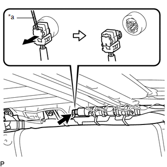
(b) Disconnect the airbag connector from the curtain shield airbag assembly.
NOTICE:
When handling the airbag connector, take care not to damage the airbag wire harness.
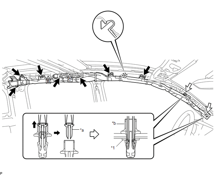
(c) Using needle nose pliers, remove the 2 pins from the 2 clips (A).
 Text in Illustration
|
*1 |
Spacer |
- |
- |
|
*a |
Pin |
*b |
Clip (A) |
HINT:
Remove the 2 clips (A) and curtain shield airbag assembly from the vehicle body as a unit.
(d) While holding the curtain shield airbag assembly, remove the 7 bolts, disengage the 2 clips (B) and 2 claws and remove the curtain shield airbag assembly. (d)Remove the 2 clips (A) and 2 spacers from the curtain shield airbag assembly.
 On-vehicle Inspection
ON-VEHICLE INSPECTION
PROCEDURE
1. INSPECT CURTAIN SHIELD AIRBAG ASSEMBLY (for Vehicle not Involved in Collision)
(a) Perform a diagnostic system check (See page
).
(b) With the curta ...
 Disposal
DISPOSAL
CAUTION / NOTICE / HINT
CAUTION:
Before performing pre-disposal deployment of any SRS part, review and closely
follow all applicable environmental and hazardous material regulations. Pre ...
Other materials:
Removal
REMOVAL
PROCEDURE
1. REMOVE FRONT DOOR SCUFF PLATE LH (for Double Cab)
2. REMOVE FRONT DOOR SCUFF PLATE LH (for Access Cab)
3. REMOVE COWL SIDE TRIM BOARD LH
4. REMOVE INSTRUMENT CLUSTER CENTER FINISH PANEL SUB-ASSEMBLY
5. REMOVE INSTRUMENT CLUSTER FINISH PANEL ASSEMBLY
6. ...
Parts Location
PARTS LOCATION
ILLUSTRATION
*A
for Vacuum Brake Booster
*B
for Hydraulic Brake Booster
*1
BRAKE ACTUATOR ASSEMBLY (SKID CONTROL ECU)
*2
BRAKE BOOSTER WITH MASTER CYLINDER ASSEMBLY (SKID CONTROL ECU)
...
Adjustment
ADJUSTMENT
PROCEDURE
1. ADJUST PARK/NEUTRAL POSITION SWITCH
(a) While pushing the shift lock release button, move the shift lever to N.
(b) Remove the bolt of the park/neutral position switch.
(c) Clean the bolt and bolt hole.
(d) Apply adhesive to 2 or 3 threads on the end of the bolt.
Adhes ...
