Toyota Tacoma (2015-2018) Service Manual: On-vehicle Inspection
ON-VEHICLE INSPECTION
PROCEDURE
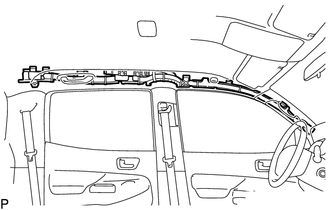
1. INSPECT CURTAIN SHIELD AIRBAG ASSEMBLY (for Vehicle not Involved in Collision)
(a) Perform a diagnostic system check (See page
.gif) ).
).
|
(b) With the curtain shield airbag assembly installed on the vehicle, perform a visual check. If there are any defects as mentioned below, replace the front pillar garnish or roof headlining assembly with a new one:
|
|
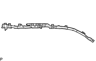
2. INSPECT CURTAIN SHIELD AIRBAG ASSEMBLY (for Vehicle Involved in Collision and Airbag not Deployed)
(a) Perform a diagnostic system check (See page
).
|
(b) With the curtain shield airbag assembly removed from the vehicle, perform a visual check. If there are any defects as mentioned below, replace the curtain shield airbag assembly with a new one:
CAUTION: For removal and installation procedures of the curtain shield airbag assembly. Be sure to follow the correct procedure. |
|
 Components
COMPONENTS
ILLUSTRATION
...
 Removal
REMOVAL
CAUTION / NOTICE / HINT
HINT:
Use the same procedure for both the RH and LH sides.
The procedure described below is for the LH side.
PROCEDURE
1. PRECAUTION
CAUTION:
B ...
Other materials:
Pressure Control Solenoid "C" Circuit Open (P079513)
DESCRIPTION
Changing from 1st to 6th is performed by the ECM turning shift solenoid valves
SL1, SL2, SL3 and SL4 on and off. If an open or short circuit occurs in any of the
shift solenoid valves, the ECM controls the remaining normal shift solenoid valves
to allow the vehicle to be operated ...
Automatic High Beam Camera (B124C)
DESCRIPTION
The main body ECU (multiplex network body ECU) detects a high beam headlight
illumination request signal of the automatic high beam system from the forward recognition
camera
DTC No.
Detection Item
DTC Detection Condition
Trouble Area
...
Air conditioning system
Adjusting the settings
■ Adjusting the temperature setting
Turn the temperature control dial clockwise (warm) or counterclockwise (cool).
If is not pressed, the system will
blow ambient temperature air or heated air.
For quick cooling, turn the temperature control dial to the MAX A/C ...
