Toyota Tacoma (2015-2018) Service Manual: Disassembly
DISASSEMBLY
CAUTION / NOTICE / HINT
HINT:
- Use the same procedures for both the LH and RH sides.
- The procedure described below is for the LH side.
PROCEDURE
1. REMOVE OUTER MIRROR
(a) Push the lower part of the mirror surface and tilt it.
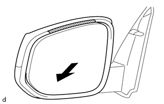 Text in Illustration
.png) |
Protective Tape |
.png) |
Push |
(b) Apply protective tape to the area shown in the illustration.
(c) Push the upper part of the mirror surface and tilt it.
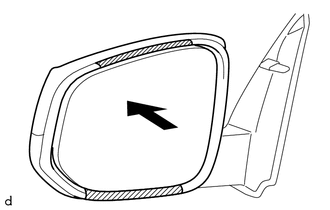 Text in Illustration
| |
Protective Tape |
| |
Push |
(d) Apply protective tape to the area shown in the illustration.
|
(e) Using a moulding remover D, disengage the 2 claws on the lower part of the outer mirror. |
|
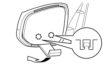
(f) Push the lower part of the mirror surface.
HINT:
If excessive force is used when pressing down the mirror surface, the 2 claws will engage again.
|
(g) Using a moulding remover D, disengage the 2 claws on the upper part of the outer mirror. |
|
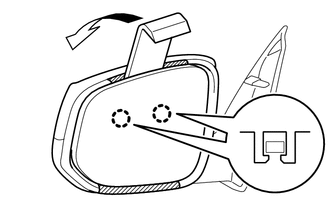
(h) Remove the protective tape.
|
(i) Disengage the clamp. |
|
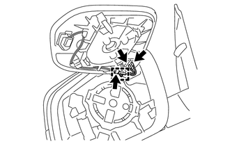
(j) Disconnect the 3 connectors to remove the outer mirror.
NOTICE:
- Do not bend the tabs excessively to prevent them from being damaged.
- If the tabs are damaged, replace the outer mirror with a new one.
- If the wire harness is damaged or any of the wires are broken, replace the outer rear view mirror assembly with a new one.
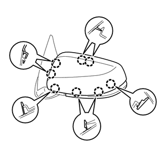
2. REMOVE OUTER MIRROR COVER (w/o Side Turn Signal Light)
|
(a) Disengage the 8 claws to remove the outer mirror cover. |
|
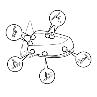
3. REMOVE OUTER MIRROR COVER (w/ Side Turn Signal Light)
|
(a) Disengage the 7 claws to remove the outer mirror cover. |
|
4. REMOVE SIDE TURN SIGNAL LIGHT ASSEMBLY (w/ Side Turn Signal Light)
.gif)
 Removal
REMOVAL
CAUTION / NOTICE / HINT
HINT:
Use the same procedures for both the LH and RH sides.
The procedure described below is for the LH side.
PROCEDURE
1. REMOVE FRONT DOOR LOWE ...
 Inspection
INSPECTION
PROCEDURE
1. INSPECT OUTER MIRROR LH
(a) Check the outer mirror heater operation.
Text in Illustration
*a
Component without harness con ...
Other materials:
Room Temperature Sensor Circuit (B1411/11)
DESCRIPTION
The cooler thermistor (room temperature sensor) is installed in the instrument
panel to detect the cabin temperature which is used to control the air conditioning
system AUTO mode. The resistance of the cooler thermistor (room temperature sensor)
changes in accordance with the cab ...
Room Light Assembly
Components
COMPONENTS
ILLUSTRATION
Removal
REMOVAL
PROCEDURE
1. REMOVE NO. 1 ROOM LIGHT ASSEMBLY
(a) Using a screwdriver with its tip wrapped in protective tape, disengage
the 4 claws to remove the No. 1 room light lens.
Text in Illustration
*a
...
Inspection
INSPECTION
PROCEDURE
1. INSPECT REAR NO. 2 POWER WINDOW REGULATOR SWITCH ASSEMBLY
*a
Component without harness connected
(Rear No. 2 Power Window Regulator Switch Assembly)
*b
Pull (Close)
*c
Push (Open)
...
