Toyota Tacoma (2015-2018) Service Manual: Removal
REMOVAL
PROCEDURE
1. REMOVE FRONT SEAT ASSEMBLY (for Driver Side)
(See page .gif) )
)
2. REMOVE FRONT SEAT ASSEMBLY (for Front Passenger Side)
(See page )
3. REMOVE SEPARATE TYPE FRONT SEAT CUSHION COVER (for Driver Side)
(See page )
4. REMOVE SEPARATE TYPE FRONT SEAT CUSHION COVER (for Front Passenger Side)
(See page )
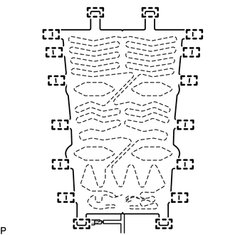
5. REMOVE FRONT SEAT CUSHION HEATER ASSEMBLY (for Driver Side)
|
(a) Cut off the 16 tag pins which fasten the front seat cushion heater assembly to the front seat cushion cover, and then remove the front seat cushion heater assembly from the front seat cushion cover. |
|
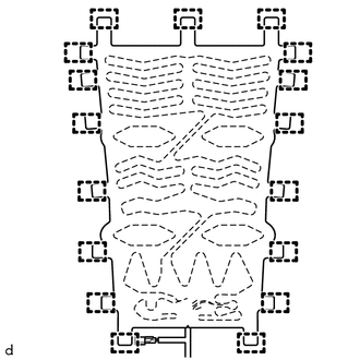
6. REMOVE FRONT SEAT CUSHION HEATER ASSEMBLY (for Front Passenger Side)
|
(a) Cut off the 17 tag pins which fasten the front seatcushion heater assembly to the front seat cushion cover, and then remove the front seat cushion heater assembly from the front seat cushion cover. |
|
 Inspection
INSPECTION
PROCEDURE
1. INSPECT FRONT SEAT CUSHION HEATER ASSEMBLY
(a) Check the operation of the front seat cushion heater assembly.
(1) Apply battery voltage and check the operation ...
 Installation
INSTALLATION
PROCEDURE
1. INSTALL FRONT SEAT CUSHION HEATER ASSEMBLY (for Driver Side)
(a) Set the front seat cushion heater assembly so that the name stamp side facing
is on the front seat cushi ...
Other materials:
Registration
REGISTRATION
PROCEDURE
1. REGISTER TRANSMITTER CODE
HINT:
The vehicle's garage door opener records transmitter codes for systems
such as garage doors, gates, entry gates, door locks, home lighting systems,
security systems or other transmitter code based systems.
The gara ...
Zero Point Calibration of Yaw Rate Sensor Undone (C1210,C1336)
DESCRIPTION
The skid control ECU (master cylinder solenoid) receives signals from the yaw
rate and acceleration (airbag sensor assembly) via the CAN communication system.
The airbag sensor assembly has a built-in yaw rate and acceleration sensor and
detects the vehicle's condition using 2 ...
Acceleration Sensor Internal Circuit (C1419,C1435)
DESCRIPTION
The skid control ECU (brake actuator assembly) receives signals from the yaw
rate and acceleration sensor (airbag sensor assembly) via the CAN communication
system.
The airbag sensor assembly has a built-in yaw rate and acceleration sensor and
detects the vehicle condition.
If t ...
