Toyota Tacoma (2015-2018) Service Manual: Removal
REMOVAL
CAUTION / NOTICE / HINT
HINT:
- Use the same procedure for both the LH and RH sides.
- The procedure described below is for the LH side.
PROCEDURE
1. REMOVE FRONT BUMPER ASSEMBLY
(See page .gif) )
)
2. REMOVE HEADLIGHT ASSEMBLY
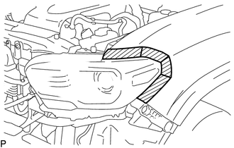
(a) Apply protective tape around the headlight assembly.
 Text in Illustration
.png) |
Protective Tape |
|
(b) Remove the bolt and 2 screws. |
|
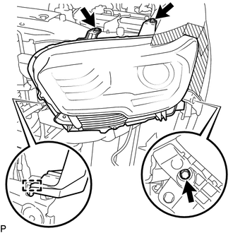
(c) Disengage the clamp to separate the headlight assembly.
(d) Disconnect the connectors to remove the headlight assembly.
 Disassembly
DISASSEMBLY
CAUTION / NOTICE / HINT
HINT:
Use the same procedure for both the LH and RH sides.
The procedure described below is for the LH side.
PROCEDURE
1. REMOVE NO. 1 HEADLI ...
 Adjustment
ADJUSTMENT
PROCEDURE
1. PREPARE VEHICLE FOR HEADLIGHT AIM ADJUSTMENT
(a) Prepare the vehicle:
Ensure that there is no damage or deformation to the body around the
headlights.
Fill t ...
Other materials:
Front Camera Module Beam Axis Not Adjusted (C1AA9)
DESCRIPTION
If forward recognition camera adjustment has not been performed or did not complete
normally after the forward recognition camera was replaced with a new one, DTC C1AA9
will be stored.
DTC No.
Detection Item
DTC Detection Condition
Troubl ...
Combination Meter
Components
COMPONENTS
ILLUSTRATION
Removal
REMOVAL
PROCEDURE
1. PRECAUTION
NOTICE:
After turning the ignition switch off, waiting time may be required before disconnecting
the cable from the negative (-) battery terminal. Therefore, make sure to read the
disconnecting the cable fro ...
Engine Control System Malfunction (C1201)
DESCRIPTION
If a malfunction in the engine control system is detected, VSC and TRAC operations
are prohibited by the fail-safe function.
DTC No.
Detection Item
DTC Detection Condition
Trouble Area
C1201
Engine Control System ...
